METER / GAUGE SYSTEM (except General Countries) Fuel Receiver Gauge Malfunction
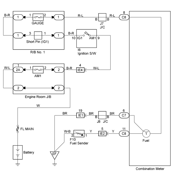
WIRING DIAGRAM
INSPECTION PROCEDURE
PROCEDURE
-
INSPECT FUEL SENDER GAUGE ASSEMBLY
-
Remove the fuel sender gauge assembly.
-
Check resistance.
-
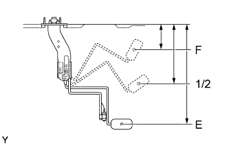
Check the float position between E and F and measure the resistance between terminals 2 and 3 (1 and 2) of the connector.
Tech Tips
( ): Except 2KD-FTV engine mode
-
Check that the resistance value changes continuously.
Standard Float level Float position mm (in.) Resistance (Ω) F 71.7 (2.1) to 79.7 (2.42) 2.4 to 3.6 1/2 173.3 (6.82) 28 to 31 E 284.7 (11.21) to 292.7 (11.53) 107.5 to 112.5
-
NG 
REPLACE FUEL SENDER GAUGE ASSEMBLY
OK 
-
-
CHECK HARNESS AND CONNECTOR
-
Check open or short of the wire harness between fuel sender gauge assembly and combination meter assembly.
-
Check open of the wire harness between fuel sender gauge assembly and body ground.
-
Check open of the wire harness between combination meter assembly and body ground.
NG
CHECK HARNESS OR CONNECTOR
OK
-
-
INSPECT FUEL RECEIVER GAUGE SUB-ASSEMBLY
-
Remove the combination meter assembly.
-
Check resistance of fuel receiver gauge.
-
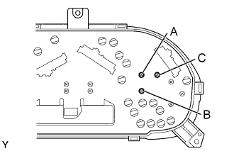
Measure resistance between terminals of the fuel receiver gauge sub-assembly, as shown in the chart.
Standard: resistance Tester connection Standard resistance (Ω) A - B Approx. 80 Ω A - C Approx. 103 Ω B - C Approx. 183 Ω
-
NG
REPLACE FUEL RECEIVER GAUGE SUB-ASSEMBLY
OK 
CHECK AND REPLACE METER CIRCUIT PLATE
-