METER / GAUGE SYSTEM (except General Countries) Speedometer Malfunction
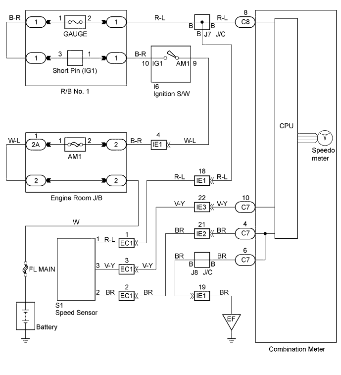
WIRING DIAGRAM
INSPECTION PROCEDURE
PROCEDURE
-
INSPECT COMBINATION METER ASSEMBLY (SP)
-
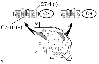
Remove the combination meter with connector still connected.
-
Check voltage.
-
Jack up one of the rear wheels.
-
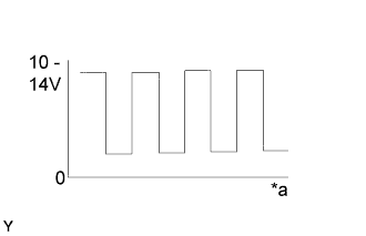
Text in Illustration *a Turn the wheel Measure voltage between terminals C7-10 and C7-4 of combination meter assembly when rear wheel is turned slowly.
Standard Voltage is generated intermittently.
-
OK 
INSPECT SPEEDOMETER ASSEMBLY Click here
NG 
-
-
INSPECT SPEEDOMETER SENSOR
-
Remove the speedometer sensor.
-
Check speedometer sensor operation.
-
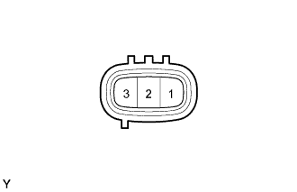
Connect the positive (+) lead from the battery to terminal 1 and negative lead to terminal 2.
-
Text in Illustration *a Turn the wheel Measure voltage between terminals 3 and 2 of the speedometer sensor.
Standard voltage Voltage is generated intermittently.
-
NG 
REPLACE SPEEDOMETER SENSOR
OK 
REPAIR OR REPLACE HARNESS OR CONNECTOR
-
-
INSPECT SPEEDOMETER ASSEMBLY
-
Remove the combination meter assembly.
-
Check resistance of speedometer assembly.
-
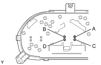
Measure resistance between terminals, as shown in the chart.
Standard: resistance Tester connection Standard resistance (Ω) A - D Approx. 160 Ω B - C Approx. 160 Ω
-
NG
REPLACE SPEEDOMETER ASSEMBLY
OK
REPLACE METER CIRCUIT PLATE
-