METER / GAUGE SYSTEM (except General Countries) Entire Combination Meter does not Operate
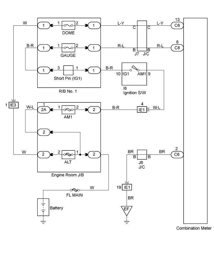
WIRING DIAGRAM
INSPECTION PROCEDURE
PROCEDURE
-
CHECK FUSE
-
Check GAUGE fuse and DOME fuse.
NG 
REPLACE FUSE
OK 
-
-
INSPECT COMBINATION METER ASSEMBLY
-
Remove the combination meter assembly with connectors still connected.
-
Check voltage.
-
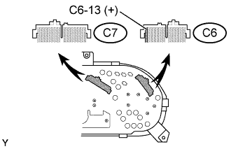
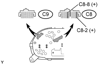
Measure voltage between C8-8 of the combination meter assembly and body ground when ignition switch is turned ON.
Standard 10 - 14 V -
Measure voltage between C6-13 of the combination meter assembly and body ground when.
-
-
Disconnect the C8 connector of combination meter.
-
Check continuity.
-
Check continuity exists between terminal C8-2 of combination meter assembly and body ground.
Standard Continuity exists.
-
NG
REPAIR OR REPLACE HARNESS OR CONNECTOR
OK
-
-
INSPECT TOTAL COUNTER MODULE ECU
-
Check malfunction disappear when a known good total counter module ECU is installed.
A B Malfunction does not disappear Malfunction disappear
B
REPLACE TOTAL COUNTER MODULE ECU
A 
CHECK AND REPLACE METER CIRCUIT PLATE
-