METER / GAUGE SYSTEM (except General Countries) ON-VEHICLE INSPECTION

-
INSPECT SPEEDOMETER
-
Check the operation.
-
Using a speedometer tester, inspect the speedometer fro allowable indication error and check the operation of the odometer.
Reference: km/h (Europe) Standard indication Allowable range 20 km/h 21 - 25 km/h 40 km/h 41.5 - 46 km/h 60 km/h 62.5 - 67 km/h 80 km/h 83 - 88 km/h 100 km/h 104 - 109 km/h 120 km/h 125 - 130.5 km/h 140 km/h 145.5 - 151.5 km/h Reference: mph (Europe) Standard indication Allowable range 20 mph 21 - 23.5 mph 40 mph 41.5 - 44 mph 60 mph 62.5 - 66 mph 80 mph 83 - 87 mph 100 mph 104 - 108.5 mph Reference: km/h (General, Australia) Standard indication Allowable range 40 km/h 36 - 44 km/h 60 km/h 54 - 66 km/h 80 km/h 72 - 88 km/h 100 km/h 90 - 110 km/h 120 km/h 108 - 132 km/h 140 km/h 144 - 176 km/h Note
Tire wear and tire over or under inflation will increase the indication error.
-
Check the deflection width of the speed meter indicator.
Reference Below 0.5 km/h / 0.3 mph
-
-
-
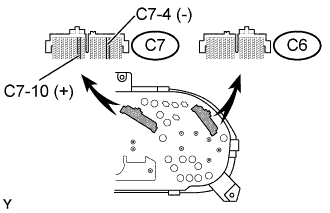
INSPECT OUTPUT SIGNAL OF VEHICLE SPEED
-
Check for standard signal.
-
While driving the vehicle at the speed of 10 km/h, check the voltage between the terminals C7-10 and C7-4 of the combination meter assembly.
Standard Fluctuation between 10 to 14 V or less is repeated 8 times within 1 sec. Note
Check it with the ignition switch ON and the connector connected.
-
-
-
INSPECT TACHOMETER
-
Check the operation
-
Connect a tune-up test tachometer, and start the engine.
Note
-
Reversing the connection of the tachometer will damage the transistors and diodes inside.
-
When removing or installing the tachometer, be careful not to drop or subject it to heavy shocks.
-
-
Compare the test and tachometer indications.
DC 13.5 V, 25 °C at (77 °F) Standard indication (r/min) Allowable range (r/min)
Data in ( ) are for reference
700 630 - 770 1,00 (900 - 1,100) 2,000 (1,850 - 2,150) 3,000 2,800 - 3,200 4,000 (3,800 - 4,200) 5,000 4,800 - 5,200
-
-
-
INSPECT FUEL RECEIVER GAUGE
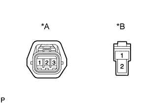
Text in Illustration *A 2KD-FTV *B Except 2KD-FTV
-
Inspect the circuit.
-
Disconnect the connector from the sender gauge.
-
Turn the ignition switch ON, then check the position of the receiver gauge needle.
Needle position EMPTY -
( ): Except 2KD-FTV engine models: Connect terminals 2 and 3 (1 and 2) on the wire harness side connector and Turn the ignition switch ON, then check the position of the receiver gauge needle.
Needle position FULL
-
-
-
INSPECT FUEL LEVEL WARNING
-
Inspect the circuit.
-
Disconnect the connector from the sender gauge.
-
Turn the ignition switch ON, check the fuel level needle indicates EMPTY and fuel level warning lights light on.
-
-
-
INSPECT WATER TEMPERATURE RECEIVER GAUGE WARNING LIGHT
-
Inspect the circuit.
-
Disconnect the connector from the sender gauge.
-
Turn the ignition switch ON, check the position of the water temperature receiver gauge needle.
Needle position COOL -
Ground terminal 2 on the wire harness side, then check the position of the water temperature receiver gauge needle.
Needle position HOT
-
-
-
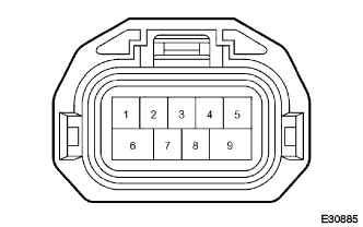
INSPECT SHIFT POSITION INDICATOR
-
Inspect the circuit.
-
Disconnect the connector from the neutral start switch.
-
Turn the ignition switch ON.
-
By connecting each terminal, short-circuit the wire harness side connector of the neutral start switch and check that the each shift position indicator light goes on.
Terminal No. Terminal name Indication position 1 - 3 PL - PB P 2 - 3 RL - PB R 5 - 3 NL - PB N 7 - 3 DL - PB D 4 - 3 2L - PB 2 8 - 3 LL - PB L
-
-
-
INSPECT LOW OIL PRESSURE WARNING LIGHT
-
Inspect the circuit.
-
Disconnect the connector from the low oil pressure switch.
-
Turn the ignition switch ON.
-
Connect the terminal of wire harness side connector and ground, then check the warning low oil pressure warning light.
Low oil pressure warning light Light on
-
-
-
INSPECT BRAKE WARNING LIGHT
-
Inspect the parking brake warning light.
-
Disconnect the connector from the parking brake switch and ground terminal on the wire harness side connector.
-
Turn the ignition switch ON and check that the warning light lights up.
-
-
-
INSPECT BRAKE FLUID LEVEL WARNING SWITCH
-
Inspect the continuity.
-
Remove the reservoir tank cap and strainer.
-
Disconnect the connector.
-
Check that the continuity exists between the terminals.
Float up (switch off) No continuity -
Use syphon, etc., to take fluid out of the reservoir tank.
-
Check that the continuity exists between the terminals.
Float down (switch on) Continuity -
Pour the fluid back in the reservoir tank.
-
-
-
INSPECT FUEL SEDIMENTER WARNING LIGHT
-
Inspect the fuel sedimenter warning light.
-
Disconnect the connector from the level warning switch and connect terminals on the wire harness side connector.
-
Turn the ignition switch ON and check that the warning light lights up.
-
-
-
INSPECT T-BELT WARNING
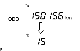
Text in Illustration *a (Normal mode) *b (T-Belt mode)
-
T-BELT mode display
-
Turn ODO/TRIP display screen to ODO, and turn the ignition switch OFF.
-
While pressing the trip switch, turn the ignition switch ON and hold it for 5 secs.
-
Release the trip switch, then press the trip switch again within 5 secs.
-
Transfer to T-BELT mode, and following initial setting value is displayed.
km : 15 (0,000 km)
mile : 9 (0,000 mile)
Tech Tips
If the meter has been replaced before, the displayed value might not be the initial setting value.
-
-
Rewriting replacement setting value
Press the trip switch and rewrite the replacement setting value.
Conditions Setting value When a belt is replaced km : 15 (0,000 km)
mile : 9 (0,000 mile)
When a meter is replaced km : ( 15 (0,000 km)) - (Km when the meter is replaced.)
mile : ( 9 (0,000 mile)) - (Mileage when the meter is replaced.)
Tech Tips
When pressing the trip switch, the displayed value is changed to 1 (0,000 km) / 1 (0,000 mile) for the first time and after this, increases in increments of 1 (0,000 km) / 1 (0,000 mile) up to 20 (0,000 km) / 20 (0,000 mile). If switch operation is not performed for more than 30 secs, the setting value will not be changed, the display screen turns to "ODO", and the mode returns to the normal mode.
-
T-BELT mode completion
Note
If T-BELT mode is completed, even though belt replacement or meter replacement has not been performed, the T-BELT warning is reset.
-
After setting the replacement setting value, hold the trip switch ON for more than 5 secs. then release the trip switch.
-
Check that the display has changed to "ODO" and warning light has gone OFF.
-
-
-
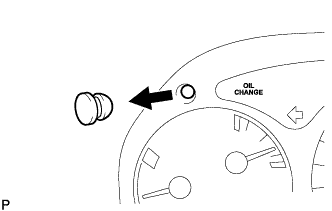
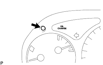
RESETTING OIL MAINTENANCE WARNING SYSTEM
Tech Tips
After an engine oil and oil filter change, even though the system has been reset, the warning light does not go out, or comes no again soon.
-
Resetting the system.
-
Turn the ignition switch ON.
-
Remove the reset switch cover from the combination meter.
-
Push the reset switch for at least one second with a thin object such as a pen tip.
-
The engine oil change reminder light will go out.
Note
Reset the system only after an engine oil and oil filter change. If you reset the system at any other time, it cannot inform you of the correct time to change the engine oil and oil filter.
Tech Tips
-
The system must also be reset if an engine oil and oil filter change is performed before the light comes on. In this case, when you push the reset switch, the light will come on. When you stop pressing the light will go out.
-
If you push the switch for too short a time the engine oil change reminder light may not go out. If this happens, reset the above procedure.
-
-
-