POWER DOOR LOCK CONTROL SYSTEM TERMINALS OF ECU
-
INTEGRATION RELAY
-
Disconnect the door control relay connector.
-
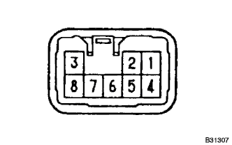
Check the voltage and continuity of each terminal on the wire harness side connector.
Tester connection Condition Specified condition 4 - Ground Constant 10 - 14 V 7 - Ground Door control switch LOCK → UNLOCK No continuity → Yes 6 - Ground Door control switch UNLOCK → LOCK No continuity → Yes 8 - Ground Constant Continuity If the value is not as specified, the input side of the master switch may be defective.
-
Check the voltage of connector terminal with connector connected.
Tester connection Condition Specified condition 1 - Ground Door control switch LOCK → UNLOCK 0 V → 10 - 14 V → 0 V 3 - Ground Door control switch UNLOCK → LOCK 0 V → 10 - 14 V → 0 V If the value is not as specified, the master switch may be defective.
-