METER / GAUGE SYSTEM (for 1KD-FTV) Engine Coolant Temperature Receiver Gauge Malfunction
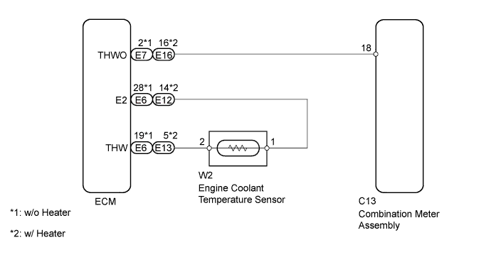
WIRING DIAGRAM
INSPECTION PROCEDURE
PROCEDURE
-
CHECK ENGINE COOLANT TEMPERATURE SENSOR CIRCUIT
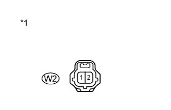
Text in Illustration *1 Front view of wire harness connector
(to Engine Coolant Temperature Sensor)
-
Disconnect Connector W2 of the engine coolant temperature sensor.
-
Check the meter needle conditions.
OK Wire Connection Switch Condition Specified Condition W2-1 - W2-2 Ignition switch ON The needle indicates above "H" All the lines are disconnected Ignition switch ON The needle indicates below "C" -
Reconnect the connector of the engine coolant temperature sensor.
NG 
CHECK HARNESS AND CONNECTOR (ENGINE COOLANT TEMPERATURE SENSOR - ECM) Click here
OK 
REPLACE ENGINE COOLANT TEMPERATURE SENSOR Click here
-
-
CHECK HARNESS AND CONNECTOR (ENGINE COOLANT TEMPERATURE SENSOR - ECM)
-
Disconnect Connector W2 of the engine coolant temperature sensor.
-
Disconnect Connector E6*1 or E12*2 and E13*2 of the ECM. *1: w/o Heater *2: w/ Heater
-
Measure the resistance according to the value(s) in the table below.
Standard resistance (w/o Heater) Tester Connection Condition Specified condition W2-2 - E6-19 (THW) Always Below 1 Ω W2-1 - E6-28 (E2) Always Below 1 Ω W2-2 or E6-19 (THW) - Body ground Always 10 kΩ or higher W2-1 or E6-28 (E2)- Body ground Always 10 kΩ or higher Standard resistance (w/ Heater) Tester Connection Condition Specified condition W2-2 - E13-5 (THW) Always Below 1 Ω W2-1 - E12-14 (E2) Always Below 1 Ω W2-2 or E13-5 (THW) - Body ground Always 10 kΩ or higher W2-1 or E12-14 (E2)- Body ground Always 10 kΩ or higher -
Reconnect the connector of the engine coolant temperature sensor.
-
Reconnect the connector(s) of the ECM.
NG 
REPAIR OR REPLACE HARNESS OR CONNECTOR
OK 
-
-
CHECK HARNESS AND CONNECTOR (ECM - COMBINATION METER ASSEMBLY)
-
Disconnect Connector C13 of the combination meter assembly.
-
Disconnect Connector E7*1 or E16*2 of the ECM. *1: w/o Heater *2: w/ Heater
-
Measure the resistance according to the value(s) in the table below.
Standard resistance (w/o Heater) Tester Connection Condition Specified condition C13-18 - E7-2 (THWO) Always Below 1 Ω C13-18 or E7-2 (THWO) - Body ground Always 10 kΩ or higher Standard resistance (w/ Heater) Tester Connection Condition Specified condition C13-18 - E16-16 (THWO) Always Below 1 Ω C13-18 or E16-16 (THWO) - Body ground Always 10 kΩ or higher -
Reconnect the connector of the combination meter assembly.
-
Reconnect the connector of the ECM.
NG
REPAIR OR REPLACE HARNESS OR CONNECTOR
OK
-
-
REPLACE COMBINATION METER ASSEMBLY
-
Replace the combination meter assembly with new one ( Click here).
NEXT
-
-
CHECK COMBINATION METER ASSEMBLY
-
Check the operation of the engine coolant temperature receiver gauge with engine running.
OK The gauge indicates appropriate temperature and indication changes according to change in temperature of the engine coolant.
NG
REPLACE ECM Click here
OK
END (COMBINATION METER ASSEMBLY IS DEFECTIVE)
-