METER / GAUGE SYSTEM (for 1KD-FTV) Engine Coolant Temperature Receiver Gauge Malfunction
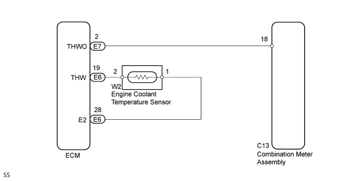
WIRING DIAGRAM
INSPECTION PROCEDURE
PROCEDURE
-
CHECK ENGINE COOLANT TEMPERATURE SENSOR CIRCUIT
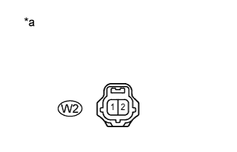
Text in Illustration *a Front view of wire harness connector
(to Engine Coolant Temperature Sensor)
-
Disconnect Connector W2 of the engine coolant temperature sensor.
-
Check the meter needle conditions.
OK Wire Connection Switch Condition Specified Condition W2-1 - W2-2 Ignition switch ON The needle indicates above "H" All the lines are disconnected Ignition switch ON The needle indicates below "C" -
Reconnect the connector of the engine coolant temperature sensor.
NG 
CHECK HARNESS AND CONNECTOR (ENGINE COOLANT TEMPERATURE SENSOR - ECM) Click here
OK 
REPLACE ENGINE COOLANT TEMPERATURE SENSOR Click here
-
-
CHECK HARNESS AND CONNECTOR (ENGINE COOLANT TEMPERATURE SENSOR - ECM)
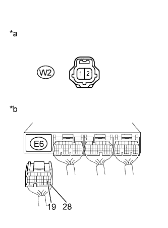
Text in Illustration *a Front view of wire harness connector
(to Engine Coolant Temperature Sensor)
*b Rear view of wire harness connector
(to ECM)
-
Disconnect Connector W2 of the engine coolant temperature sensor.
-
Disconnect Connector E6 of the ECM.
-
Measure the resistance according to the value(s) in the table below.
Standard resistance Tester Connection Condition Specified condition W2-2 - E6-19 (THW) Always Below 1 Ω W2-1 - E6-28 (E2) Always Below 1 Ω W2-2 or E6-19 (THW) - Body ground Always 10 kΩ or higher W2-1 or E6-28 (E2)- Body ground Always 10 kΩ or higher -
Reconnect the connector of the engine coolant temperature sensor.
-
Reconnect the connector of the ECM.
NG 
REPAIR OR REPLACE HARNESS OR CONNECTOR
OK 
-
-
CHECK HARNESS AND CONNECTOR (ECM - COMBINATION METER ASSEMBLY)
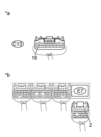
Text in Illustration *a Rear view of wire harness connector
(to Combination Meter Assembly)
*b Rear view of wire harness connector
(to ECM)
-
Disconnect Connector C13 of the combination meter assembly.
-
Disconnect Connector E7 of the ECM.
-
Measure the resistance according to the value(s) in the table below.
Standard resistance Tester Connection Condition Specified condition C13-18 - E7-2 (THWO) Always Below 1 Ω C13-18 or E7-2 (THWO) - Body ground Always 10 kΩ or higher -
Reconnect the connector of the combination meter assembly.
-
Reconnect the connector of the ECM.
NG
REPAIR OR REPLACE HARNESS OR CONNECTOR
OK
REPLACE COMBINATION METER ASSEMBLY Click here
-