METER / GAUGE SYSTEM (for 1KD-FTV) Fuel Gauge Malfunction
DESCRIPTION
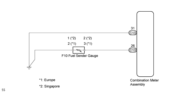
The combination meter assembly controls the fuel receiver gauge in accordance with the resistance of the fuel sender gauge that varies depending on the amount of fuel remaining in the fuel tank.
WIRING DIAGRAM
INSPECTION PROCEDURE
PROCEDURE
-
CHECK FUEL SENDER GAUGE CIRCUIT
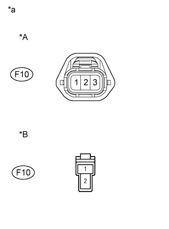
Text in Illustration *A for Europe *B for Singapore *a Front view of wire harness connector
(to Fuel Sender Gauge Assembly)
-
Disconnect the F10 fuel sender gauge connector.
-
Check the meter indicator condition.
Standard Europe Wire connection Condition Specified Condition F10-2 - F10-3 Short circuit (Ignition switch ON) Fuel gauge indicates "F" or more (Combination meter) Singapore Wire connection Condition Specified Condition F10-1 - F10-2 Short circuit (Ignition switch ON) Fuel gauge indicates "F" or more (Combination meter) -
Measure the voltage.
Standard voltage Europe Tester Connection Condition Specified Condition 3 - Body ground Ignition switch ON 4 to 7 V Singapore Tester Connection Condition Specified Condition 2 - Body ground Ignition switch ON 4 to 7 V -
Reconnect the connector.
NG 
CHECK HARNESS AND CONNECTOR (FUEL SENDER GAUGE ASSEMBLY - COMBINATION METER ASSEMBLY) Click here
OK 
-
-
INSPECT FUEL SENDER GAUGE
-
Remove the fuel sender gauge assembly.
-
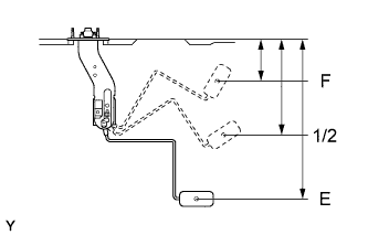
Check that the float position is between E and F and measure resistance between terminals 2 and 3*1 or 1 and 2*2 of connector.
*1: Europe
*2: Singapore
-
Measure the resistance.
Standard resistance Float level Float position mm (in.) Specified Condition F 75.7 (2.98) +/- 4 (0.16) 3.0 +/- 0.6 Ω 1/2 173.3 (6.82) 29.5 +/- 1.5 Ω E 288.7 (11.37) +/- 4 (0.16) 110.0 +/- 2.5 Ω -
Reinstall the fuel sender gauge assembly.
NG 
REPLACE FUEL SENDER GAUGE ASSEMBLY
OK 
REPLACE COMBINATION METER ASSEMBLY
-
-
CHECK HARNESS AND CONNECTOR (FUEL SENDER GAUGE ASSEMBLY - COMBINATION METER ASSEMBLY)
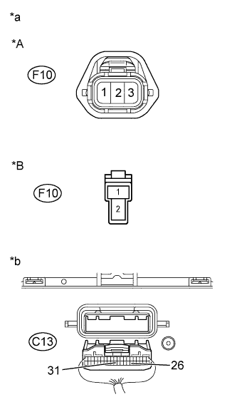
Text in Illustration *A for Europe *B for Singapore *a Front view of wire harness connector
(to Fuel Sender Gauge Assembly)
*b Rear view of wire harness connector
(to Combination Meter Assembly)
-
Disconnect the C13 combination meter assembly connector.
-
Disconnect the F10 fuel sender gauge connector.
-
Measure the resistance.
Standard resistance Europe Tester connection Specified condition C13-26 - F10-3 Below 1 Ω C13-31 - F10-2 Below 1 Ω F10-2 - Body ground Below 1 Ω C13-26 or F10-3 - Body ground 10 kΩ or higher Singapore Tester connection Specified condition C13-26 - F10-2 Below 1 Ω C13-31 - F10-1 Below 1 Ω F10-1 - Body ground Below 1 Ω C13-26 or F10-2 - Body ground 10 kΩ or higher -
Reconnect the connectors.
NG
REPAIR OR REPLACE HARNESS OR CONNECTOR
OK
REPLACE COMBINATION METER ASSEMBLY
-