HEADLIGHT DIMMER SWITCH INSPECTION

-
TURN SIGNAL SWITCH ASSEMBLY
-
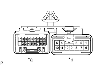
Text in Illustration *a Connector B *b Connector A Inspect light control switch continuity.
-
Check that the continuity between terminals at each switch position, as shown in the chart.
Switch operation Tester connection Specified condition OFF - No continuity TAIL B17 - B19 Continuity HEAD B17 - B9 - B8 Continuity
-
-
Inspect headlight dimmer switch continuity.
-
Check that the continuity between terminals at each switch position, as shown in the chart.
Switch operation Tester connection Specified condition FLASH B16 - A5 - A12 Continuity LOW BEAM A4 - A12 Continuity HI BEAM A5 - A12 Continuity
-
-
Inspect turn signal switch continuity.
-
Check that the continuity between terminals at each switch position, as shown in the chart.
Switch operation Tester connection Specified condition Right turn B15 - B12 Continuity Neutral - No continuity Left turn A2 - B12 Continuity
-
-
Inspect front fog light switch continuity. (w/Fog light)
-
Check that the continuity between terminals at each switch position, as shown in the chart.
Switch operation Tester connection Specified condition OFF B6 - B18 No continuity ON B6 - B18 Continuity
-
-