WIPER SWITCH INSTALLATION

-
INSTALL WINDSHIELD WIPER SWITCH ASSEMBLY
-
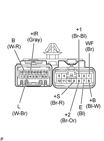
Install the connector terminals for connector.
Note
Do not mistake arrange connector pins.
-
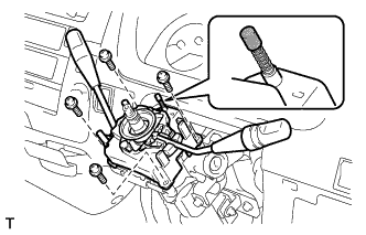
Install the windshield wiper switch assembly, using 3 screws.
-
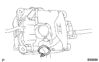
Install the new cord clamp.
-
After installing the cord clamp, cut it off so that the length from the binding point will be 1 to 3 mm.
-
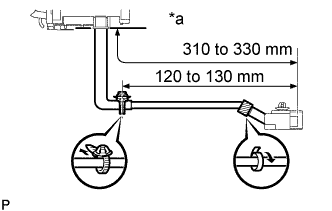
Text in Illustration *a Combination Lever Switch assembly Installed Position Using 2 wire harness clamps, bind the wire harness, and tape the wire harness. (w/o SRS airbag)
-
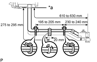
Text in Illustration *a Combination Lever Switch assembly Installed Position Using 2 wire harness clamps, bind the wire harness, and tape the wire harness. (w SRS airbag)
-
-
INSPECT SPIRAL CABLE SUB-ASSEMBLY (W/ SRS AIRBAG)
-
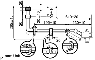
As shown in illustration, bind the 2 wire harnesses with the 2 wire harness clamps.
-
Put new vinyl tape 2 or 3 times around the place shown in the diagram.
-
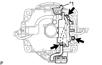
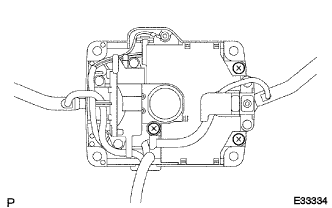
Text in Illustration *1 Cord Clamp As shown in illustration, locate the wire harness of spiral cable sub-assembly along the back side of turn signal switch assembly.
-
Connect the connector to the spiral cable sub-assembly.
-
Install the headlamp dimmer switch to the turn signal switch assembly with the 3 screws.
-
wire harness with a new cord clamp.
-
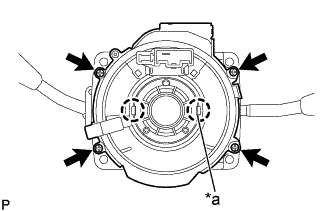
Text in Illustration *a Project Part Combine the hole part of cancel cam with the project part of spiral cable sub-assembly, then install with the 4 screws.
Note
When replacing the spiral cable sub-assembly with new one, remove the lock pin before installing the steering wheel assembly.
-
-
PLACE FRONT WHEELS FACING STRAIGHT AHEAD
-
INSTALL SPIRAL CABLE SUB-ASSEMBLY (W/ SRS AIRBAG)
-
As shown in illustration, bind the 2 wire harnesses with the 2 wire harness clamps.
-
Put new vinyl tape 2 or 3 times around the place shown in the diagram.
-
Text in Illustration *1 Cord Clamp As shown in illustration, locate the wire harness of spiral cable sub-assembly along the back side of turn signal switch assembly.
-
Connect the connector to the spiral cable sub-assembly.
-
Install the headlamp dimmer switch to the turn signal switch assembly with the 3 screws.
-
wire harness with a new cord clamp.
-
Text in Illustration *a Project Part Combine the hole part of cancel cam with the project part of spiral cable sub-assembly, then install with the 4 screws.
Note
When replacing the spiral cable sub-assembly with new one, remove the lock pin before installing the steering wheel assembly.
-
-
INSTALL TURN SIGNAL SWITCH ASSEMBLY
-
Install the turn signal switch assembly with 4 screws.
Note
In the model without SRS airbag, lightly coat the horn contact with the grease.
-
Connect the connectors and wire harness clamps.
-
-
INSTALL STEERING COLUMN COVER UPR
-
Install the steering column cover UPR with the 2 screws.
-
-
INSTALL STEERING COLUMN COVER LWR
-
Install the steering column cover LWR with the clip and 2 screws.
-
-
CENTER SPIRAL CABLE (W/ SRS AIRBAG)
-
Check that the ignition switch is OFF.
-
Check that the battery negative terminal is disconnected.
Note
Do not start the operation for 90 seconds after removing the terminal.
-
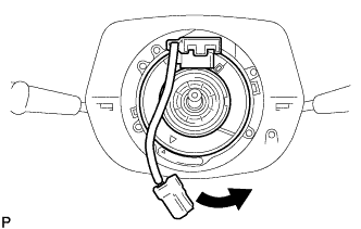
Turn the cable counterclockwise by hand until it becomes harder to turn.
Tech Tips
The cable will rotate about 3.5 turns to either left or right of the center.
-
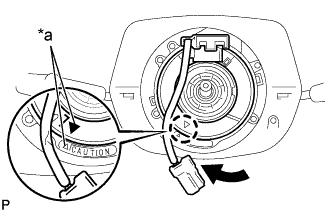
Text in Illustration *a Matchmarks Then rotate the cable clockwise about 3.5 turns to align the marks.
-
-
INSTALL STEERING WHEEL ASSEMBLY
-
Align the matchmarks on the steering wheel assembly with the one on the steering main shaft.
-
Install the steering wheel set nut.
- Torque:
- 50 N*m { 510 kgf*cm, 37 ft.*lbf }
-
-
INSPECT STEERING WHEEL CENTER POINT
-
INSPECT HORN BUTTON ASSEMBLY (W/ SRS AIRBAG)
-
Do a diagnostic system check Click here.
-
Do a visual check which includes the following items with the horn button assembly (with airbag) removed from the vehicle.
-
Check cuts, minute cracks or marked discoloration on the horn button assembly top surface and in the grooved portion.
-
Check cuts and cracks in wire harness, and chipping in connectors.
-
Check the deformation on the steering wheel.
-
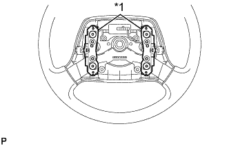
Text in Illustration *1 Contact Plate Check the deformation on the horn button contact plate of the steering wheel assembly.
Tech Tips
-
If the horn button contact plate of the steering wheel assembly is deformed, never repair it. Always replace the steering wheel pad with a new one.
-
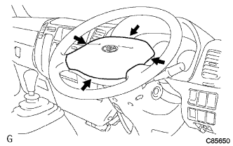
There should be no interference between the horn button assembly and steering wheel assembly, and the clearance should be uniform all the way around when the new horn button assembly is installed on the steering wheel assembly.
CAUTION:
For removal and installation of the horn button assembly, see page 60-11, and be sure to follow the correct procedure.
-
-
-
INSTALL HORN BUTTON ASSEMBLY (W/ SRS AIRBAG)
-
INSTALL HORN BUTTON ASSEMBLY (W/O SRS AIRBAG)
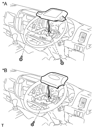
Text in Illustration *A Non-Tilt Steering Column *B Tilt Steering Column
-
Non-Tilt Steering Column:
-
Connect the horn button connector.
-
Install the 2 screws and horn button assembly.
-
-
Tilt Column Steering:
-
Connect the horn button connector.
-
Install the bolt and horn button assembly.
- Torque:
- 2.0 N*m { 20 kgf*cm, 18 in.*lbf }
-
-
-
INSPECT SRS WARNING LIGHT (W/ SRS AIRBAG)