FRONT AIRBAG SENSOR REMOVAL

-
PRECAUTION
-
BATTERY NEGATIVE TERMINAL
-
PLACE FRONT WHEELS FACING STRAIGHT AHEAD
-
REMOVE HORN BUTTON ASSEMBLY
-
REMOVE STEERING WHEEL ASSEMBLY
-
Remove the steering wheel assembly set nut.
-
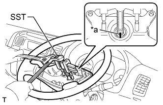
Text in Illustration *a Matchmark Place matchmarks on the steering wheel assembly and main shaft assembly.
-
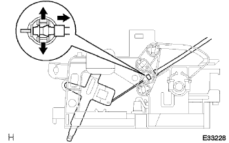
Using SST, remove the steering wheel assembly.
- SST
- 09950-50013 ( 09951-05010, 09952-05010, 09953-05010, 09954-05021 )
-
-
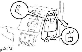
REMOVE INSTRUMENT CLUSTER FINISH PANEL SUB-ASSEMBLY CENTER
-
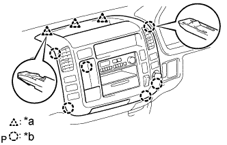
Text in Illustration *a 3 Clips *b 6 Claws Disengage the 3 clips and 6 claws.
-
Disconnect the connectors and remove the instrument cluster finish panel sub-assembly center.
-
-
REMOVE HEATER CONTROL LEVER KNOB (W/ HEATER))
-
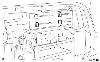
Remove the 4 heater control lever knobs.
-
-
REMOVE HEATER CONTROL NAME PLATE (W/ HEATER))
-
Text in Illustration *a 4 Claws Release the 4 claw fittings, remove the heater control name plate.
-
-
REMOVE HEATER OR BOOST VENTILATOR CONTROL ASSEMBLY (W/ HEATER))
-
Spread the clamp's claws of the defroster damper control cable and disconnect the inner cable.
-
Spread the clamp's claws of the air inlet damper control cable and disconnect the inner cable.
-
Text in Illustration *a Claw Release the claw fitting, remove the heater blower switch assembly and bulb.
-
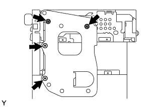
Remove the 3 screws and heater or boost ventilator control assembly.
-
Spread the clamp's claws of the air mix damper control cable and disconnect the inner cable.
-
Disconnect the connector, remove the heater or boost ventilator control assembly.
-
-
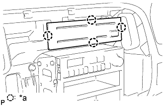
REMOVE RADIO BRACKET NO. 1 AND NO. 2
-
Remove the 4 screws and radio bracket No. 1.
-
-
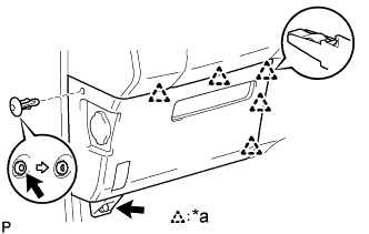
REMOVE GLOVE COMPARTMENT DOOR ASSEMBLY
-
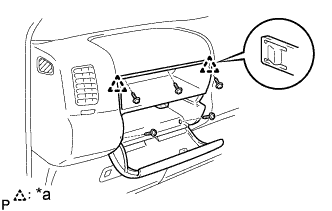
Text in Illustration *a 2 Claws Remove the 5 screws<D>.
-
Disengage the 2 claws and remove the glove compartment door assembly.
-
-
REMOVE INSTRUMENT COVER LWR (W/O HEATER))
-
Text in Illustration *a 3 Clips Disengage the 3 clips and remove the instrument cover LWR.
-
-
REMOVE INSTRUMENT COVER LWR (W/ HEATER))
-
Text in Illustration *a 5 Clips Remove the clip and bolt.
-
Disengage the 5 clips and remove the instrument cover LWR.
-
-
REMOVE INSTRUMENT COVER LOWER CENTER (W/ HEATER))
-
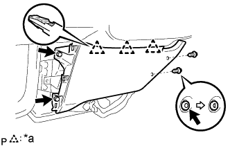
Text in Illustration *a 3 Clips Remove the 2 clips and 2 bolts.
-
Disengage the 3 clips and remove the instrument cover lower center.
-
-
REMOVE INSTRUMENT CLUSTER FINISH PANEL
-
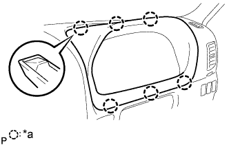
Text in Illustration *a 6 Claws Using a moulding remover, disengage the 6 claws and remove the instrument cluster finish panel.
-
-
REMOVE COMBINATION METER ASSEMBLY
-
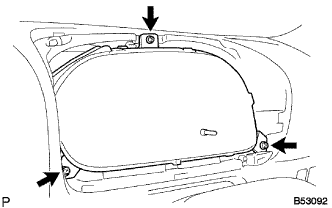
Remove the 3 screws.
-
Disconnect the connectors and remove the combination meter assembly.
-
-
REMOVE OIL RESERVOIR TANK COVER RH (RHD STEERING POSITION TYPE))
-
Text in Illustration *a 6 Claws Disengage the 6 claws and remove the oil reservoir tank cover RH.
-
-
REMOVE OIL RESERVOIR TANK COVER LH (LHD STEERING POSITION TYPE)
-
REMOVE INSTRUMENT PANEL SUB-ASSEMBLY
-
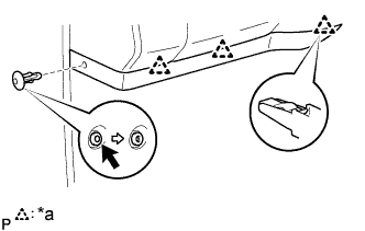
Remove the 2 clips.
-
Remove the 2 nuts<F> and 7 bolts<A><B>.
-
Disconnect the connectors and remove the instrument panel sub-assembly.
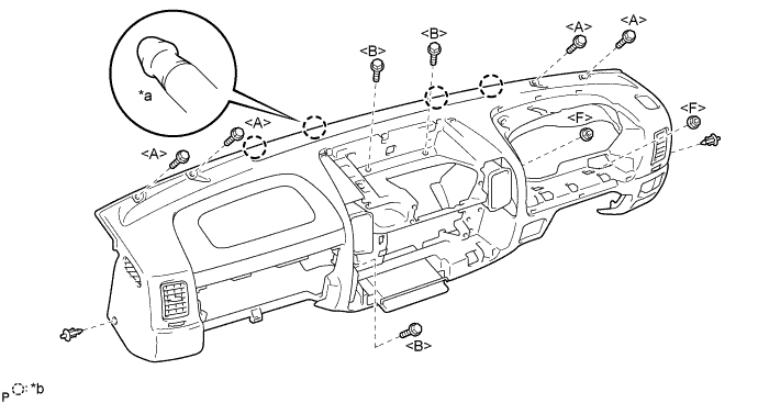
Text in Illustration *a Pin *b 4 Pins
-
-
REMOVE RADIATOR GRILLE
-
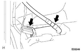
SEPARATE HEATER WATER INLET HOSE B
-
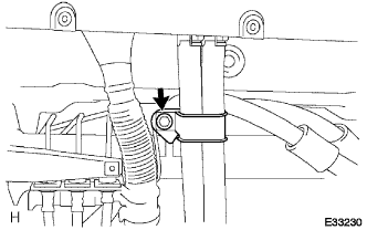
Remove the bolt and heater water bracket.
-
Slide the clip and disconnect the heater water inlet hose B.
-
-
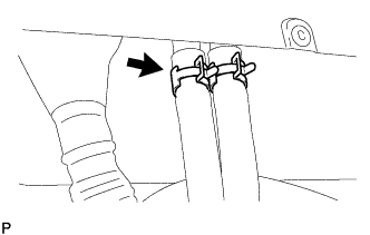
SEPARATE HEATER WATER OUTLET HOSE B
-
Slide the clip and disconnect the heater water outlet hose B.
-
-
SEPARATE DOOR CONTROL RECEIVER (W/ WIRELESS DOOR LOCK)
-
SEPARATE BRAKE MASTER CYLINDER RESERVOIR SUB-ASSEMBLY
-
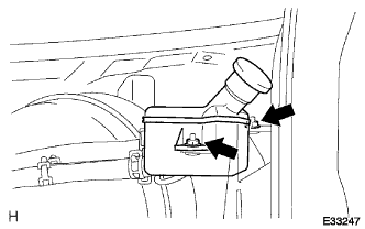
Remove the 2 nuts and disconnect bracket master cylinder reservoir sub-assembly.
-
-
REMOVE INSTRUMENT PANEL BRACE SUB-ASSEMBLY NO. 1
-
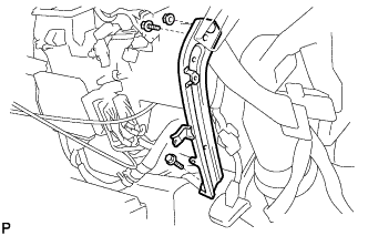
Remove the 2 bolts, nut and instrument panel brace sub- assembly No. 1.
-
-
REMOVE FRONT DOOR SCUFF PLATE RH
-
REMOVE STEERING COLUMN COVER UPR
-
REMOVE STEERING COLUMN COVER LWR
-
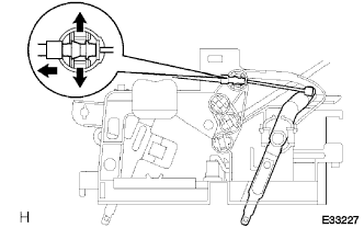
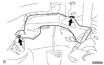
SEPARATE STEERING COLUMN TUBE LOWER
-
Turn the floor carpet off until the bolts holding the steering column tube lower can be seen.
-
Remove the 4 bolts, separate the steering column tube lower from the body.
-
-
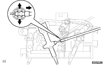
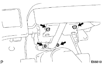
SEPARATE STEERING COLUMN ASSEMBLY
-
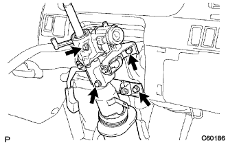
Remove the 4 bolts, separate the steering column assembly from the steering column tube sub-assembly lower, and tilt it to the backside of the vehicle.
-
-
REMOVE AIR DUCT NO. 2 (LHD STEERING POSITION TYPE))
-
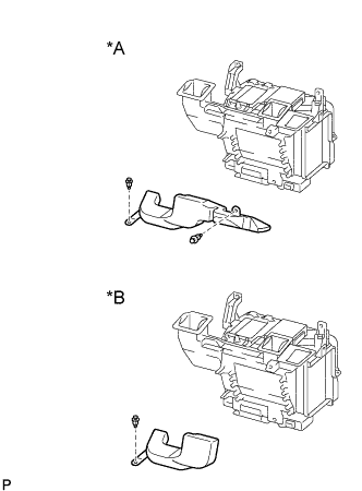
Text in Illustration *A w/ Cold area *B w/o Cold area w/ Cold area:
Remove the 2 clips and air duct No. 2.
-
w/o Cold area:
Remove the clip and air duct No. 2.
-
-
REMOVE AIR DUCT NO. 1
-
Remove the 2 clips and air duct No. 1.
-
-
REMOVE STEERING COLUMN TUBE ASSEMBLY LOWER
-
Remove the 4 bolts and disconnect the steering column tube assembly lower.
-
-
REMOVE INSTRUMENT PANEL REINFORCEMENT
-
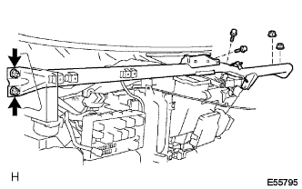
Remove the 2 bolts, 4 nuts and instrument panel reinforcement.
-
-
REMOVE WINDSHIELD WASHER JAR ASSEMBLY
-
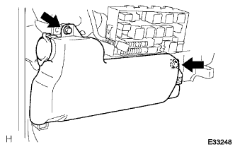
Remove the 2 bolts and windshield washer jar.
-
Disconnect the hose and connector from washer pump.
-
-
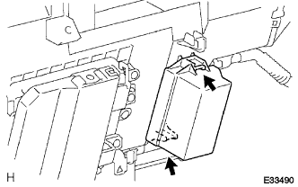
REMOVE AIR DUCT SUB-ASSEMBLY NO. 1
-
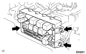
Remove the 3 bolts and disconnect the relay block assembly.
-
Remove the screw and disconnect the relay block assembly.
-
Remove the bolt.
-
Disconnect the blower resistor connector.
-
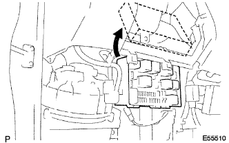
Disconnect the relay block assembly.
-
Remove the 2 bolts, 4 screws and air duct sub-assembly No. 1.
-
-
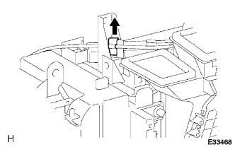
REMOVE DEFROSTER NOZZLE ASSEMBLY LOWER
-
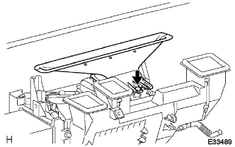
Remove the screw and defroster nozzle assembly LWR.
-
-
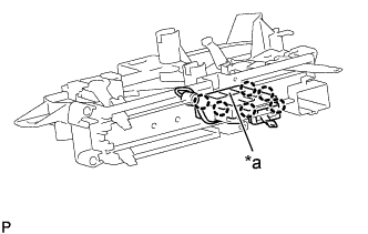
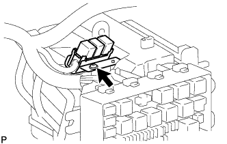
SEPARATE SKID CONTROL ECU ASSEMBLY
-
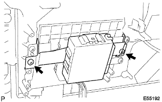
Remove the 2 screws and disconnect the skid control ECU assembly.
-
-
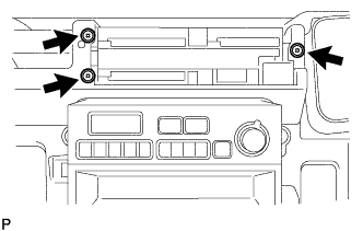
REMOVE ECM (2KD-FTV ENGINE TYPE))
-
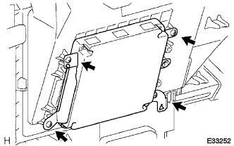
Remove the 4 screws and disconnect the ECM.
-
-
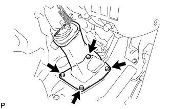
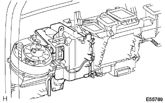
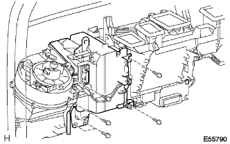
REMOVE HEATER RADIATOR ASSEMBLY
-
Release the 2 claws, disconnect the connector.
-
Disconnect the outer cable from the clamp.
-
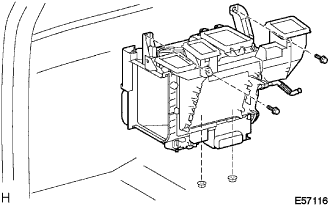
Remove the 2 bolts, 2 nuts and heater radiator assembly.
-
-
REMOVE SEAT AIR BAG NO. 1 COVER RH
-
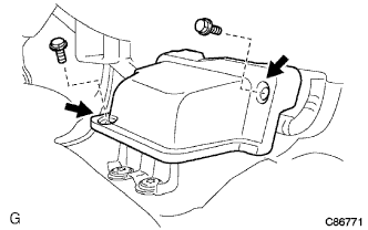
Remove the 2 bolts and seat airbag No. 1 cover RH.
-
-
REMOVE AIR BAG SENSOR ASSEMBLY NO. 2
-
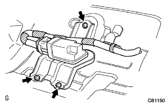
Disconnect the connector of airbag sensor assembly No. 2.
-
Using a torx socket wrench (T40), remove the 3 torx screws and airbag sensor assembly No. 2.
-