STEERING PAD ON-VEHICLE INSPECTION

-
HORN BUTTON ASSEMBLY (VEHICLES NOT INVOLVED IN COLLISION)
-
Do a diagnostic system check Click here.
-
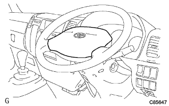
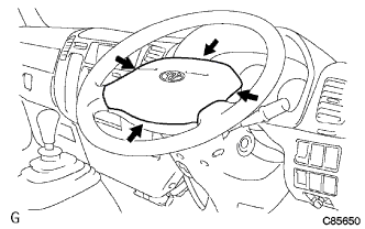
Do a visual check which includes the following item with the horn button assembly (with airbag) installed in the vehicle. Check cuts, minute cracks or marked discoloration on the horn button assembly top surface and in the grooved portion.
-
-
HORN BUTTON ASSEMBLY (VEHICLE INVOLVED IN COLLISION AND AIRBAG IS NOT DEPLOYED)
-
Do a diagnostic system check Click here.
-
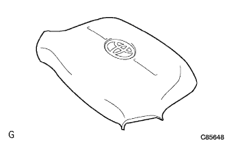
Do a visual check which includes the following items with the horn button assembly (with airbag) removed from the vehicle.
-
Check cuts, minute cracks or marked discoloration on the horn button assembly top surface and in the grooved portion.
-
Check cuts and cracks in wire harness, and chipping in connectors.
-
Check the deformation on the steering wheel.
-
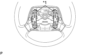
Text in Illustration *1 Contact Plate Check the deformation on the horn button contact plate of the steering wheel assembly.
Tech Tips
-
If the horn button contact plate of the steering wheel assembly is deformed, never repair it. Always replace the steering wheel pad with a new one.
-
There should be no interference between the horn button assembly and steering wheel assembly, and the clearance should be uniform all the way around when the new horn button assembly is installed on the steering wheel assembly.
CAUTION:
For removal and installation of the horn button assembly, see page 60-11, and be sure to follow the correct procedure.
-
-
-
HORN BUTTON ASSEMBLY (VEHICLE INVOLVED IN COLLISION AND AIRBAG IS DEPLOYED)
-
Do a diagnostic system check Click here.
-
Do a visual check which includes the following item with the horn button assembly (with airbag) removed from the vehicle.
Check the damage on the spiral cable connector and wire harness.
Tech Tips
There should be no interference between the horn button assembly and steering wheel assembly, and the clearance should be uniform all the way around when the new horn button assembly is installed on the steering wheel assembly.
-
-
WIRE HARNESS AND CONNECTOR (VEHICLE NOT INVOLVED IN COLLISION)
-
Do a diagnostic system check Click here.
-
-
WIRE HARNESS AND CONNECTOR (VEHICLE INVOLVED IN COLLISION)
-
Do a diagnostic system check Click here.
-
Check breaks in all wires of the SRS wire harness, and exposed conductors.
-
Check to see if the SRS wire harness connectors are cracked or chipped.
Tech Tips
The SRS wire harness is integrated with the instrument panel wire harness assembly. All the connectors in the system are a standard yellow color.
-