AIRBAG SYSTEM TC and CG Terminal Circuit
DESCRIPTION
DTC indication mode is set by connecting Terminals TC and CG of the DLC3. The DTCs are indicated through SRS warning light blinking patterns.
Tech Tips
If the warning lights blink continuously, there may be a ground short in the wiring of Terminal TC of the DLC3 or an internal ground short of TC in any ECU.
WIRING DIAGRAM
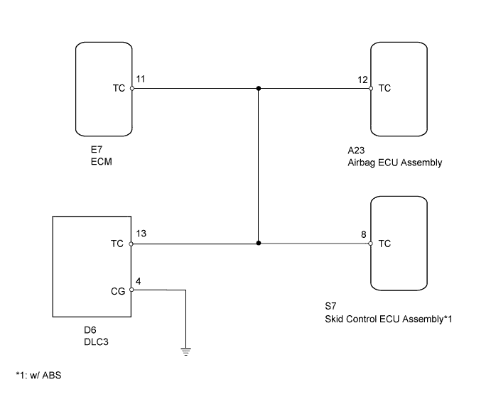
INSPECTION PROCEDURE
PROCEDURE
-
CHECK WIRE HARNESS (DLC3 - AIRBAG ECU ASSEMBLY)
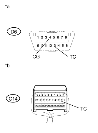
Text in Illustration *a Front view of wire harness connector
(DLC3)
*b Rear view of wire harness connector
(to Airbag ECU Assembly)
-
Turn the ignition switch off.
-
Disconnect the cable from the negative (-) battery terminal, and wait for at least 90 seconds.
-
Disconnect Connector A23.
-
Measure the resistance according to the value(s) in the table below.
Standard Resistance Tester Connection Condition Specified Condition D3-13 (TC) - A23-12 (TC) Always Below 1 Ω D3-4 (CG) - Body ground Always Below 1 Ω
NG 
REPLACE COWL WIRE
OK 
-
-
CHECK WIRE HARNESS (DLC3 - AIRBAG ECU ASSEMBLY)
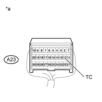
Text in Illustration *a Rear view of wire harness connector
(to Airbag ECU Assembly)
-
Confirm that Connector A23 is disconnected.
-
Measure the resistance according to the value(s) in the table below.
Standard Resistance Tester Connection Condition Specified Condition A23-12 (TC) - Body ground Always 1 MΩ or higher
NG 
CHECK WIRE HARNESS (DLC3 - AIRBAG ECU ASSEMBLY) Click here
OK 
REPLACE AIRBAG ECU ASSEMBLY Click here
-
-
CHECK WIRE HARNESS (DLC3 - AIRBAG ECU ASSEMBLY)
Text in Illustration *a Rear view of wire harness connector
(to Airbag ECU Assembly)
-
Confirm that Connector A23 is disconnected.
-
Disconnect Connector E7.
-
Measure the resistance according to the value(s) in the table below.
Standard Resistance Tester Connection Condition Specified Condition A23-12 (TC) - Body ground Always 1 MΩ or higher
NG
CONFIRM VEHICLE CONFIGURATION Click here
OK
REPLACE ECM Click here
-
-
CONFIRM VEHICLE CONFIGURATION
-
Confirm the configuration of the vehicle and select an appropriate procedure from the table below.
Result Configuration Proceed to w/ ABS A w/o ABS B
B
REPLACE COWL WIRE
A
-
-
CHECK WIRE HARNESS (DLC3 - AIRBAG ECU ASSEMBLY)
Text in Illustration *a Rear view of wire harness connector
(to Airbag ECU Assembly)
-
Confirm that Connector A23 is disconnected.
-
Disconnect Connector S7.
-
Measure the resistance according to the value(s) in the table below.
Standard Resistance Tester Connection Condition Specified Condition A23-12 (TC) - Body ground Always 1 MΩ or higher
NG
REPLACE COWL WIRE
OK
REPLACE SKID CONTROL ECU ASSEMBLY Click here
-