AIRBAG SYSTEM, Diagnostic DTC:B1900/73, B1901/73, B1902/73, B1903/73

| DTC Code | DTC Name |
|---|---|
| B1900/73 | Short in Front Driver Side Pretensioner Squib Circuit |
| B1901/73 | Open in Front Driver Side Pretensioner Squib Circuit |
| B1902/73 | Short to GND in Front Driver Side Pretensioner Squib Circuit |
| B1903/73 | Short to B+ in Front Driver Side Pretensioner Squib Circuit |
DESCRIPTION
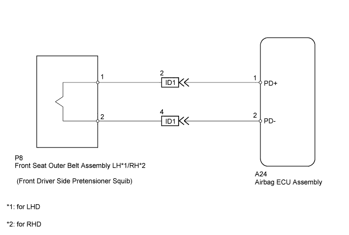
The front driver side pretensioner squib circuit consists of the airbag ECU assembly and the front seat outer belt assembly (Driver side). The airbag ECU assembly sends deployment signals to the front driver side pretensioner squib through this circuit when the deployment conditions are met.
The following DTCs are recorded in the memory when a malfunction is detected in the front driver side pretensioner squib circuit.
| DTC No. | DTC Detection Condition | Trouble Area(s) |
|---|---|---|
| B1900/73 | Short in the front driver side pretensioner squib circuit |
|
| B1901/73 | Open in the front driver side pretensioner squib circuit |
|
| B1902/73 | Short to ground in the front driver side pretensioner squib circuit |
|
| B1903/73 | Short to B+ in the front driver side pretensioner squib circuit |
|
*1: for LHD
*2: for RHD
WIRING DIAGRAM
INSPECTION PROCEDURE
Tech Tips
-
If only past DTCs are indicated, perform troubleshooting using the symptom simulation method Click here.
-
Perform the simulation method by selecting the Check Mode (Signal Check) using the intelligent tester. After selecting the Check Mode (Signal Check), perform the simulation method by shaking each connector of the airbag system or driving the vehicle on on various roads, such as city roads and rough roads Click here.
-
Once the cause of the trouble has been eliminated, clear the DTCs which were stored during troubleshooting and then check for DTCs to confirm whether the system is sound Click here.
PROCEDURE
-
CHECK CONNECTORS
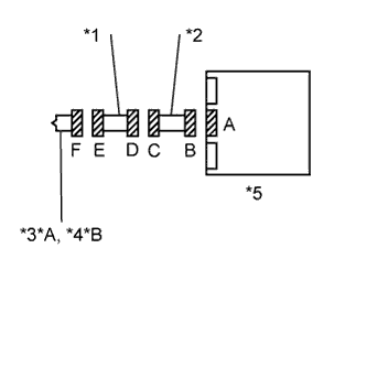
Text in Illustration *A for LHD *B for RHD *1 Floor Wire *2 Cowl Wire *3 Front Seat Outer Belt Assembly LH *4 Front Seat Outer Belt Assembly RH *5 Airbag ECU Assembly
-
Turn the ignition switch off.
-
Disconnect the cable from the negative (-) battery terminal, and wait for at least 90 seconds.
-
Check that the connectors are properly connected to the front seat outer belt assembly, the floor wire and the airbag ECU assembly.
OK The connectors are properly connected and secured. Tech Tips
After confirming that the connectors are secured in the correct positions, proceed to the next check.
-
Disconnect the connectors from the front seat outer belt assembly, the floor wire and the airbag ECU assembly.
-
Check that the terminals of the connectors are not damaged.
OK The terminals are not damaged. -
Check that the short springs of the activation prevention mechanism are not damaged.
OK The short springs are not damaged. Tech Tips
The short springs are located in Connectors B and F.
NG 
REPLACE WIRE HARNESSES AND COMPONENTS WITH DAMAGED CONNECTORS
OK 
-
-
CHECK FRONT SEAT OUTER BELT ASSEMBLY DRIVER SIDE (DRIVER SIDE FRONT PRETENSIONER SQUIB)
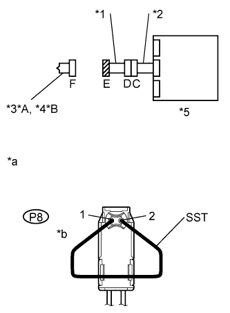
Text in Illustration *A for LHD *B for RHD *1 Floor Wire *2 Cowl Wire *3 Front Seat Outer Belt Assembly LH *4 Front Seat Outer Belt Assembly RH *5 Airbag ECU Assembly *a Front view of wire harness connector
(to Front Seat Outer Belt Assembly)
*b Connector E
-
Confirm that the cable is disconnected from the negative (-) battery terminal.
-
Connect the cowl wire to the airbag ECU assembly and the floor wire.
-
Connect SST (resistance 2.1 Ω) to Connector E.
- SST
- 09843-18060
CAUTION:
Do not connect an electrical tester to the front seat outer belt assembly (Driver side front pretensioner squib) to measure the resistance. Accidental deployment of the SRS could lead to a serious injury.
Note
-
Do not forcibly insert the SST into the connector. It may damage the terminals of the connector and cause an imperfect connection.
-
Align the pin of the SST with one of the terminals of the connector when connecting them.
-
Connect the cable to the negative (-) battery terminal.
-
Turn the ignition switch to ON, and wait for at least 60 seconds.
-
Clear the DTCs stored in the memory Click here.
-
Turn the ignition switch off.
-
Turn the ignition switch to ON, and wait for at least 60 seconds.
-
Check for DTCs Click here.
OK DTCs B1900, B1901, B1902, B1903 and 73 are not indicated. Tech Tips
DTCs other than DTC B1900, B1901, B1902, B1903 and 73 may be indicated at this time, but they are not related to this check.
NG 
CHECK DRIVER SIDE FRONT PRETENSIONER SQUIB CIRCUIT (AIRBAG ECU ASSEMBLY - FRONT SEAT OUTER BELT ASSEMBLY) Click here
OK 
REPLACE FRONT SEAT OUTER BELT ASSEMBLY DRIVER SIDE Click here
-
-
CHECK DRIVER SIDE FRONT PRETENSIONER SQUIB CIRCUIT (AIRBAG ECU ASSEMBLY - FRONT SEAT OUTER BELT ASSEMBLY)
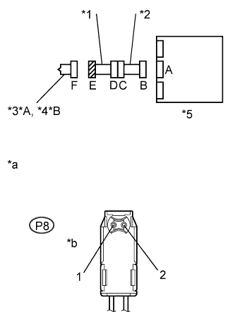
Text in Illustration *A for LHD *B for RHD *1 Floor Wire *2 Cowl Wire *3 Front Seat Outer Belt Assembly LH *4 Front Seat Outer Belt Assembly RH *5 Airbag ECU Assembly *a Front view of wire harness connector
(to Front Seat Outer Belt Assembly)
*b Connector E
-
Turn the ignition switch off.
-
Disconnect the cable from the negative (-) battery terminal, and wait for at least 90 seconds.
-
Disconnect the connector from the Airbag ECU assembly.
-
Connect the cable to the negative (-) battery terminal.
-
Turn the ignition switch to ON.
-
Check for a short to B+ in the circuit.
-
Measure the voltage according to the value(s) in the table below.
Standard Voltage Tester Connection Switch Condition Specified Condition P8-1 - Body ground Ignition switch ON Below 1 V P8-2 - Body ground Ignition switch ON Below 1 V
-
-
Turn the ignition switch off.
-
Disconnect the cable from the negative (-) battery terminal, and wait for at least 90 seconds.
-
Check for an open circuit.
-
Measure the resistance according to the value(s) in the table below.
Standard Resistance Tester Connection Condition Specified Condition P8-1 - P8-2 Always Below 1 Ω
-
-
Release the built-in activation prevention mechanism of Connector B Click here.
-
Check for a short to ground in the circuit.
-
Measure the resistance according to the value(s) in the table below.
Standard Resistance Tester Connection Condition Specified Condition P8-1 - Body ground Always 1 MΩ or higher P8-2 - Body ground Always 1 MΩ or higher
-
-
Check for a short between lines in the circuit.
-
Measure the resistance according to the value(s) in the table below.
Standard Resistance Tester Connection Condition Specified Condition P8-1 - P8-2 Always 1 MΩ or higher
-
-
Reset the activation prevention mechanism of Connector B to its normal state.
NG
CHECK COWL WIRE Click here
OK
REPLACE AIRBAG ECU ASSEMBLY Click here
-
-
CHECK COWL WIRE
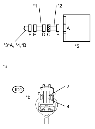
Text in Illustration *A for LHD *B for RHD *1 Floor Wire *2 Cowl Wire *3 Front Seat Outer Belt Assembly LH *4 Front Seat Outer Belt Assembly RH *5 Airbag ECU Assembly *a Rear view of wire harness connector
(to Floor Wire)
*b Connector C
-
Confirm that the cable is disconnected from the negative (-) battery terminal.
-
Disconnect the connector of the cowl wire from the floor wire.
-
Connect the cable to the negative (-) battery terminal.
-
Turn the ignition switch to ON.
-
Check for a short to B+ in the circuit.
-
Measure the voltage according to the value(s) in the table below.
Standard Voltage Tester Connection Switch Condition Specified Condition ID1-2 - Body ground Ignition switch ON Below 1 V ID1-4 - Body ground Ignition switch ON Below 1 V
-
-
Turn the ignition switch off.
-
Disconnect the cable from the negative (-) battery terminal, and wait for at least 90 seconds.
-
Check for an open circuit.
-
Measure the resistance according to the value(s) in the table below.
Standard Resistance Tester Connection Condition Specified Condition ID1-2 - ID1-4 Always Below 1 Ω
-
-
Release the built-in activation prevention mechanism of Connector B Click here.
-
Check for a short to ground in the circuit.
-
Measure the resistance according to the value(s) in the table below.
Standard Resistance Tester Connection Condition Specified Condition ID1-2 - Body ground Always 1 MΩ or higher ID1-4 - Body ground Always 1 MΩ or higher
-
-
Check for a short between lines in the circuit.
-
Measure the resistance according to the value(s) in the table below.
Standard Resistance Tester Connection Condition Specified Condition ID1-2 - ID1-4 Always 1 MΩ or higher
-
-
Reset activation prevention mechanism of Connector B to its normal state.
NG
REPLACE COWL WIRE
OK
REPLACE FLOOR WIRE
-