AIRBAG SYSTEM, Diagnostic DTC:B1662/45

| DTC Code | DTC Name |
|---|---|
| B1662/45 | Indicator Light Circuit Malfunction |
DESCRIPTION
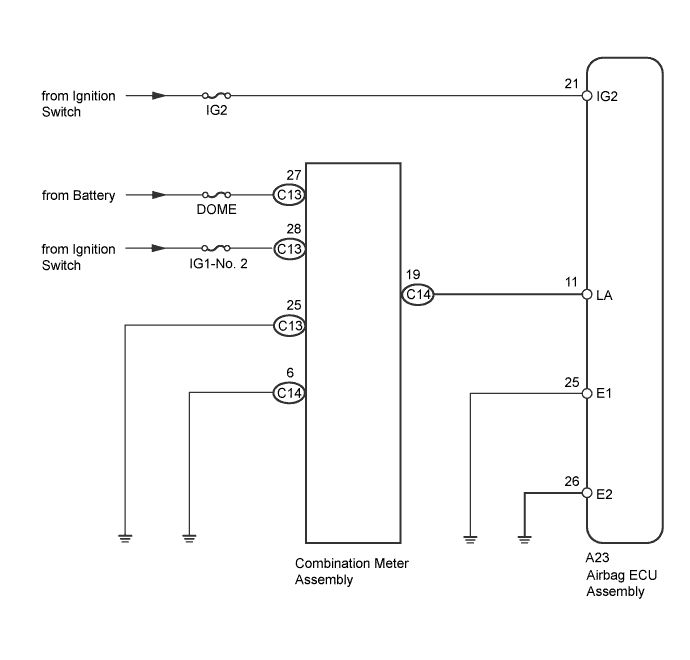
The SRS warning indicator light circuit consists of the airbag ECU assembly and combination meter assembly. The airbag ECU assembly controls the operation of the SRS warning light located in the combination meter assembly. When the SRS is normal, the SRS warning light comes on for approximately 6 seconds after the ignition switch is turned from off to ON, and then goes off automatically. If there is a malfunction in the SRS, the SRS warning light comes on to inform the driver.
| DTC No. | DTC Detection Condition | Trouble Area(s) |
|---|---|---|
| B1662/45 | Malfunction in the SRS warning indicator light circuit |
|
WIRING DIAGRAM
INSPECTION PROCEDURE
Tech Tips
-
If only past DTCs are indicated, perform troubleshooting using the symptom simulation method Click here.
-
Once the cause of the trouble has been eliminated, clear the DTCs which were stored during troubleshooting and then check for DTCs to confirm whether the system is sound Click here.
PROCEDURE
-
CHECK BATTERY VOLTAGE
-
Measure the voltage of the battery.
Standard Voltage 11 to 14 V
NG 
CHECK CHARGING SYSTEM AND BATTERY Click here
OK 
-
-
CHECK CONNECTORS
-
Turn the ignition switch off.
-
Disconnect the cable from the negative (-) battery terminal, and wait for at least 90 seconds.
-
Check that Connector A23 is properly connected to the airbag ECU assembly.
OK The connector is properly connected and secured. Tech Tips
After confirming that the connector is secured in the correct position, proceed to the next check.
-
Check that Connector C14 is properly connected to the combination meter assembly.
OK The connector is properly connected. Tech Tips
After confirming that the connector is secured in the correct position, proceed to the next check.
-
Disconnect Connectors A23 and C14 from the airbag ECU assembly and the combination meter assembly.
-
Check that the terminals of the connector are not damaged.
OK The terminals are not damaged.
NG
REPLACE WIRE HARNESSES AND COMPONENTS WITH DAMAGED CONNECTORS
OK
-
-
CHECK WIRE HARNESS (AIRBAG ECU ASSEMBLY - COMBINATION METER ASSEMBLY)
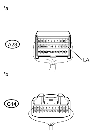
Text in Illustration *a Rear view of wire harness connector
(to Airbag ECU Assembly)
*b Rear view of wire harness connector
(to Combination Meter Assembly)
-
Confirm that Connector A23 is disconnected.
-
Confirm that Connector C14 is disconnected.
-
Measure the resistance according to the value(s) in the table below.
Standard Resistance Tester Connection Condition Specified Condition A23-11 (LA) - C14-19 Always Below 1 Ω A23-11 (LA) - Body ground Always 1 MΩ or higher
NG
REPLACE COWL WIRE
OK
-
-
CHECK AIRBAG ECU ASSEMBLY (LIGHT DRIVE SIGNAL)
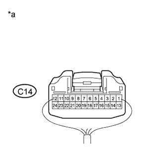
Text in Illustration *a Rear view of wire harness connector
(to Combination Meter Assembly)
-
Connect Connector A23.
-
Confirm that Connector C14 is disconnected.
-
Connect the cable to the negative (-) battery terminal.
-
Measure the voltage according to the value(s) in the table below.
Standard Voltage Tester Connection Switch Condition Specified Condition C14-19 - Body ground Ignition switch ON
(For approximately 6 seconds after turning the ignition switch to ON)
Below 1V Ignition switch ON
(After the period mentioned above)
8 to 14 V
NG
REPLACE AIRBAG ECU ASSEMBLY Click here
OK 
REPLACE COMBINATION METER ASSEMBLY Click here
-