AIRBAG SYSTEM, Diagnostic DTC:B160C/AA, B160D/AA, B160E/AA

| DTC Code | DTC Name |
|---|---|
| B160C/AA | Front Floor Bus Initialization Incomplete |
| B160D/AA | Lost Communication with Front Floor Satellite Sensor Bus |
| B160E/AA | Front Floor Satellite Sensor Bus Initialization Incomplete |
DESCRIPTION
The front floor satellite sensor bus circuit consists of the No. 2 airbag sensor assembly and airbag ECU assembly.
The No. 2 airbag sensor assembly detects impacts applied to the vehicle and sends signals to the airbag ECU assembly to determine whether or not the SRS parts should be deployed.
The following DTCs are recorded in the memory when a malfunction is detected in the front floor satellite sensor bus circuit.
| DTC No. | DTC Detection Condition | Trouble Area(s) |
|---|---|---|
| B160C/AA | Failure in initialization of the front floor satellite sensor bus |
|
| B160D/AA | Interruption in communication with No. 2 airbag sensor assembly |
|
| B160E/AA | Failure in initialization of No. 2 airbag sensor assembly on bus |
|
WIRING DIAGRAM
Refer to "DTC B160A/39 Front Floor Sensor Malfunction" Click here.
INSPECTION PROCEDURE
Tech Tips
-
If only past DTCs are indicated, perform troubleshooting using the symptom simulation method Click here.
-
Once the cause of the trouble has been eliminated, clear the DTCs which were stored during troubleshooting and then check for DTCs to confirm whether the system is sound Click here.
PROCEDURE
-
CHECK CONNECTORS
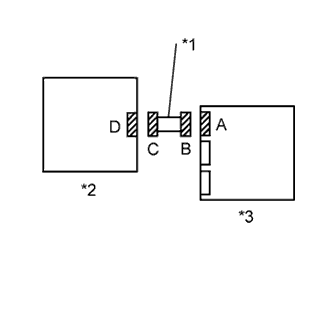
Text in Illustration *1 Cowl Wire *2 No. 2 Airbag Sensor Assembly *3 Airbag ECU Assembly
-
Turn the ignition switch off.
-
Disconnect the cable from the negative (-) battery terminal, and wait for at least 90 seconds.
-
Check that the connectors are properly connected to the No. 2 airbag sensor assembly and the airbag ECU assembly.
OK The connectors are properly connected and secured. Tech Tips
After confirming that the connectors are secured in the correct positions, proceed to the next check.
-
Disconnect the connectors from the No. 2 airbag sensor assembly and the airbag ECU assembly.
-
Check that the terminals of the connectors are not damaged.
OK The terminals are not damaged.
NG 
REPLACE WIRE HARNESSES AND COMPONENTS WITH DAMAGED CONNECTORS
OK 
-
-
CHECK COWL WIRE (AIRBAG ECU ASSEMBLY - NO. 2 AIRBAG SENSOR ASSEMBLY)
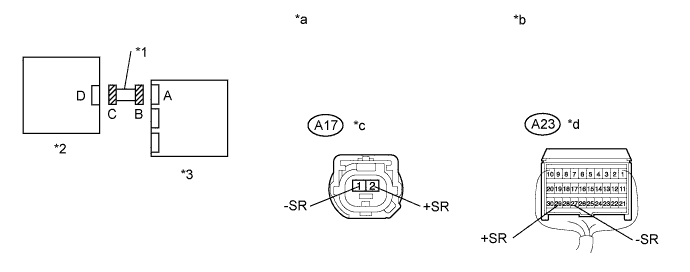
Text in Illustration *1 Cowl Wire *2 No. 2 Airbag Sensor Assembly *3 Airbag ECU Assembly - - *a Front view of wire harness connector
(to No. 2 Airbag Sensor Assembly)
*b Rear view of wire harness connector
(to Airbag ECU Assembly)
*c Connector C *d Connector B
-
Confirm that Connectors A17 and A23 are disconnected.
-
Connect the cable to the negative (-) battery terminal.
-
Turn the ignition switch to ON.
-
Check for a short to B+ in the circuit.
-
Measure the voltage according to the value(s) in the table below.
Standard Voltage Tester Connection Switch Condition Specified Condition A17-1 (-SR) - Body ground Ignition switch ON Below 1 V A17-2 (+SR) - Body ground Ignition switch ON Below 1 V
-
-
Turn the ignition switch off.
-
Disconnect the cable from the negative (-) battery terminal, and wait for at least 90 seconds.
-
Check for an open circuit.
-
Measure the resistance according to the value(s) in the table below.
Standard Resistance Tester Connection Condition Specified Condition A17-1 (-SR) - A23-27 (-SR) Always Below 1 Ω A17-2 (+SR) - A23-29 (+SR) Always Below 1 Ω
-
-
Check for a short to ground in the circuit.
-
Measure the resistance according to the value(s) in the table below.
Standard Resistance Tester Connection Condition Specified Condition A17-1 (-SR) - Body ground Always 1 MΩ or higher A17-2 (+SR) - Body ground Always 1 MΩ or higher
-
-
Check for a short in the circuit.
-
Measure the resistance according to the value(s) in the table below.
Standard Resistance Tester Connection Condition Specified Condition A17-1 (-SR) - A17-2 (+SR) Always 1 MΩ or higher
-
NG
REPLACE COWL WIRE
OK
-
-
CHECK NO. 2 AIR BAG SENSOR ASSEMBLY
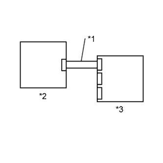
Text in Illustration *1 Cowl Wire *2 No. 2 Airbag Sensor Assembly *3 Airbag ECU Assembly
-
Confirm that the cable are disconnected from the negative (-) battery terminal.
-
Confirm that Connectors A17 and A23 are disconnected.
-
Temporarily replace the No. 2 airbag sensor assembly with a new one or with one with the same part number which is working correctly.
-
Connect the connectors to the No. 2 airbag sensor assembly and the airbag ECU assembly.
-
Connect the cable to the negative (-) battery terminal.
-
Turn the ignition switch to ON, and wait for at least 60 seconds.
-
Clear the DTCs stored in the memory Click here.
-
Turn the ignition switch off.
-
Turn the ignition switch to ON, and wait for at least 60 seconds.
-
Check for DTCs Click here.
OK DTCs B160C, B160D, B160E and AA are not indicated. Tech Tips
DTCs other than DTC B160C, B160D, B160E and AA may be indicated at this time, but they are not related to this check.
NG
REPLACE AIRBAG ECU ASSEMBLY Click here
OK 
REPLACE NO. 2 AIRBAG SENSOR ASSEMBLY Click here
-