AIRBAG SYSTEM, Diagnostic DTC:B1100/31

| DTC Code | DTC Name |
|---|---|
| B1100/31 | Airbag ECU Assembly Malfunction |
DESCRIPTION
The airbag ECU assembly consists of a airbag ECU assembly, safing sensor, drive circuit, diagnosis circuit and ignition control, etc.
It receives signals from the airbag sensor, judges whether or not the SRS must be activated, and detects diagnosis system malfunction.
DTC B1100/31 is recorded when occurrence of a malfunction in the airbag ECU assembly is detected.
| DTC No. | DTC Detecting Condition | Trouble Area |
|---|---|---|
| B1100/31 |
|
|
INSPECTION PROCEDURE
Tech Tips
When a malfunction code other than code B1100/31 is displayed at the same time, first repair the malfunction indicated by the malfunction code other than code B1100/31.
PROCEDURE
-
CHECK VOLTAGE AT IG2 OF AIRBAG ECU ASSEMBLY
-

Disconnect negative (-) terminal cable from the battery, and wait at least for 90 seconds.
-
Disconnect the connectors of the airbag ECU assembly.
-
Connect negative (-) terminal cable to the battery, and turn the ignition switch to ON.
-
Measure the voltage between body ground and terminal IG2 of the airbag ECU assembly connector.
OK Voltage: 10 - 14 V
NG 
REPAIR OR REPLACE COWL WIRE
OK 
-
-
CHECK AIR BAG ECU ASSEMBLY
- SST
- 09843-18040
-
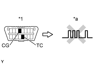
Text in Illustration *1 DLC3 *a DTC B1100/31 Disconnect negative (-) terminal cable from the battery, and wait at least for 90 seconds.
-
Connect the connectors of all the SRS components.
-
Clear the DTC stored in memory Click here.
-
Turn the ignition switch to LOCK, and wait at least for 20 seconds.
-
Turn the ignition switch to ON, and wait at least for 60 seconds.
-
Repeat operation in step (a) and (b) at least 5 times.
-
Check the DTC Click here.
OK DTC B1100/31 is not output. Tech Tips
Codes other than code B1100/31 may be output at this time, but they are not relevant to this check.
NG
REPLACE AIR BAG ECU ASSEMBLY
OK 
USE SIMULATION METHOD TO CHECK