AIRBAG SYSTEM, Diagnostic DTC:B0100/13

| DTC Code | DTC Name |
|---|---|
| B0100/13 | Short in Driver Side Squib Circuit |
DESCRIPTION
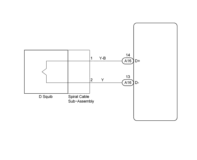
The D squib circuit consists of the airbag ECU assembly, spiral cable sub-assembly and horn button assembly.
It causes the airbag to deploy when the airbag deployment conditions are satisfied.
DTC B0100/13 is recorded when a short is detected in the D squib circuit.
| DTC No. | DTC Detecting Condition | Trouble Area |
|---|---|---|
| B0100/13 |
|
|
WIRING DIAGRAM
INSPECTION PROCEDURE
PROCEDURE
-
CHECK D SQUIB CIRCUIT (AIRBAG ECU ASSEMBLY - HORN BUTTON ASSEMBLY)
-
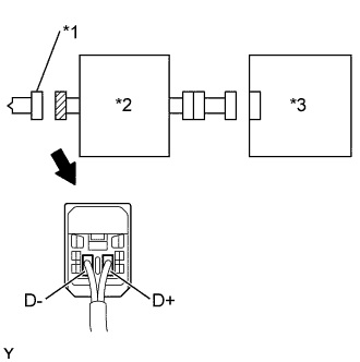
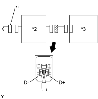
Text in Illustration *1 D Squib *2 Spiral Cable Sub-Assembly *3 Airbag ECU Assembly Disconnect negative (-) terminal cable from the battery, and wait at least for 90 seconds.
-
Disconnect the connectors between the airbag ECU assembly and the horn button assembly.
-
Release the airbag activation prevention mechanism of the connector (on the airbag ECU assembly side) between the airbag ECU assembly and the spiral cable sub-assembly Click here.
-
For the connector (on the spiral cable sub-assembly side ) between the spiral cable sub-assembly and the horn button assembly, measure the resistance between D+ and D-.
OK Resistance: 1 MΩ or Higher
NG 
CHECK COWL WIRE (AIRBAG ECU ASSEMBLY - SPIRAL CABLE SUB-ASSEMBLY) Click here
OK 
-
-
CHECK AIR BAG ECU ASSEMBLY
- SST
- 09843-18040
-
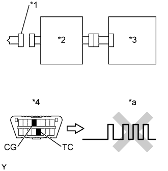
Text in Illustration *1 D Squib *2 Spiral Cable Sub-Assembly *3 Airbag ECU Assembly *4 DLC3 *a DTC B0100/13 Connect the connector to the airbag ECU assembly.
-
Connect negative (-) terminal cable to the battery, and wait at least for 2 seconds.
-
Turn the ignition switch to ON, and wait at least for 20 seconds.
-
Clear the DTC stored in memory Click here.
-
Turn the ignition switch to LOCK, and wait at least for 20 seconds.
-
Turn the ignition switch to ON, and wait at least for 60 seconds.
-
Check the DTC Click here.
OK DTC B0100/13 is not output. Tech Tips
Codes other than code B0100/13 may be output at this time, but they are not relevant to this check.
NG 
REPLACE AIR BAG ECU ASSEMBLY
OK
-
CHECK D SQUIB
- SST
- 09843-18040
-
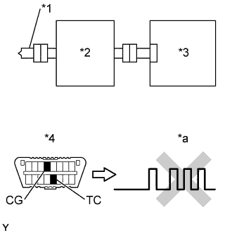
Text in Illustration *1 D Squib *2 Spiral Cable Sub-Assembly *3 Airbag ECU Assembly *4 DLC3 *a DTC B0100/13 Turn the ignition switch to LOCK.
-
Disconnect negative (-) terminal cable from the battery, and wait at least for 90 seconds.
-
Connect the horn button assembly connector.
-
Connect negative (-) terminal cable to the battery, and wait at least for 2 seconds.
-
Turn the ignition switch to LOCK, and wait at least for 20 seconds.
-
Turn the ignition switch to ON, and wait at least for 20 seconds.
-
Clear the DTC stored in memory Click here.
-
Turn the ignition switch to LOCK, and wait at least for 20 seconds.
-
Turn the ignition switch to ON, and wait at least for 60 seconds.
-
Check the DTC Click here.
OK DTC B0100/13 is not output. Tech Tips
Codes other than code B0100/13 may be output at this time, but they are not relevant to this check.
NG
REPLACE HORN BUTTON ASSEMBLY
OK 
USE SIMULATION METHOD TO CHECK
-
CHECK COWL WIRE (AIRBAG ECU ASSEMBLY - SPIRAL CABLE SUB-ASSEMBLY)
-
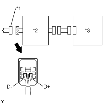
Text in Illustration *1 D Squib *2 Spiral Cable Sub-Assembly *3 Airbag ECU Assembly Disconnect the connectors of the cowl wire harness.
-
Release the airbag activation prevention mechanism of the connector (on the airbag ECU assembly side) between the airbag ECU assembly and the spiral cable sub-assembly Click here.
-
For the connector (on the spiral cable sub-assembly side ) between the spiral cable sub-assembly and airbag ECU assembly, measure the resistance between D+ and D-.
OK Resistance: 1 MΩ or Higher
NG
REPAIR OR REPLACE COWL WIRE
OK
-
-
CHECK SPIRAL CABLE SUB-ASSEMBLY
-
Text in Illustration *1 D Squib *2 Spiral Cable Sub-Assembly *3 Airbag ECU Assembly Release the airbag activation prevention mechanism of the spiral cable sub-assembly connector (on the airbag ECU assembly side) Click here.
-
For the connector (on the spiral cable sub-assembly side ) between the spiral cable sub-assembly and the horn button assembly, measure the resistance between D+ and D-.
OK Resistance: 1 MΩ or Higher
NG
REPLACE SPIRAL CABLE SUB-ASSEMBLY
OK
USE SIMULATION METHOD TO CHECK
-