BLOWER UNIT REMOVAL

-
REMOVE RADIATOR GRILLE
-
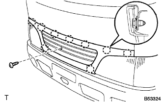
Remove the screws.
-
Disengage the meshing of clips to remove the radiator grille.
-
-
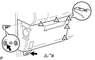
REMOVE CLEARANCE LAMP LENS AND BODY LH
-
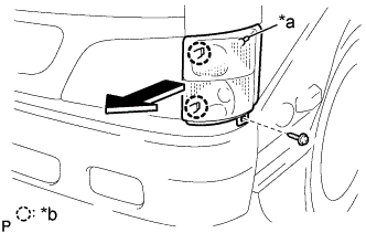
Text in Illustration *a Pin *b Claw Remove the screw.
-
Pull out the clearance light lens & body LH forward, then disconnect the pin of body side.
-
Disconnect the connectors.
-
-
REMOVE HEADLAMP UNIT ASSEMBLY LH
-
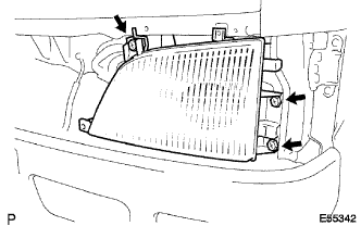
Remove the 3 screws.
-
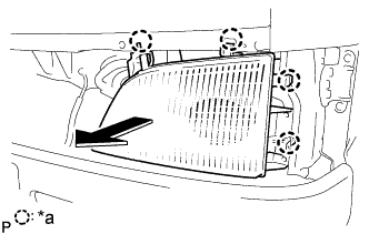
Text in Illustration *a Claw Release the 4 claws.
-
Disconnect connectors.
-
Pull out the headlight assembly LH forward and remove the headlight assembly LH.
-
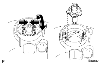
Remove the socket cover.
-
Release the set spring, remove the headlight bulb No.1.
-
-
REMOVE HEATER AIR FILTER
-
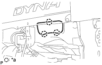
Text in Illustration *a 3 Claws Remove the 3 claws and heater air filter.
-
-
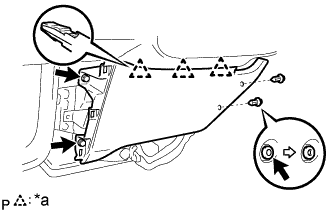
REMOVE GLOVE COMPARTMENT DOOR ASSEMBLY
-
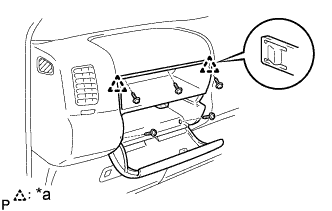
Text in Illustration *a 2 Claws Remove the 5 screws<D>.
-
Disengage the 2 claws and remove the glove compartment door assembly.
-
-
REMOVE INSTRUMENT COVER LWR
-
Text in Illustration *a 5 Clips Remove the clip and bolt.
-
Disengage the 5 clips and remove the instrument cover LWR.
-
-
REMOVE INSTRUMENT COVER LOWER CENTER
-
Text in Illustration *a 3 Clips Remove the 2 clips and 2 bolts.
-
Disengage the 3 clips and remove the instrument cover lower center.
-
-
REMOVE WINDSHIELD WASHER JAR ASSEMBLY
-
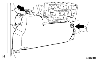
Remove the 2 bolts and windshield washer jar.
-
Disconnect the hose and connector from washer pump.
-
-
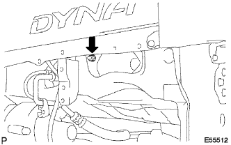
REMOVE AIR DUCT SUB-ASSEMBLY NO. 1
-
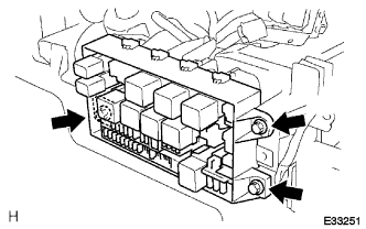
Remove the 3 bolts and disconnect the relay block assembly.
-
Remove the screw and disconnect the relay block assembly.
-
Remove the bolt.
-
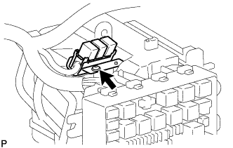
Disconnect the blower resistor connector.
-
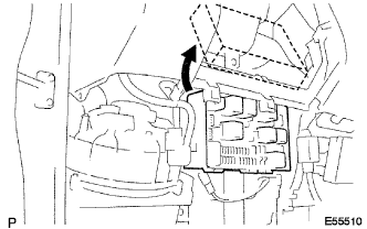
Disconnect the relay block assembly.
-
Remove the 2 bolts, 4 screws and air duct sub-assembly No. 1.
-
-
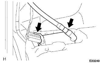
SEPARATE AIR INLET DAMPER CONTROL CABLE SUB-ASSEMBLY
-
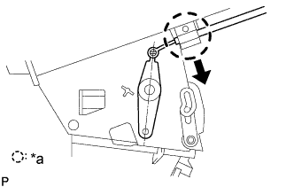
Text in Illustration *a Clamp Disconnect the outer cable from the clamp.
-
Remove the inner cable.
-
-
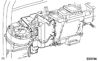
REMOVE HEATER BLOWER ASSEMBLY FRONT
-
Disconnect the heater blower motor connector.
-
Disconnect the 2 connector holders from the heater blower assembly front.
-
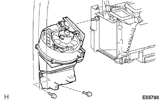
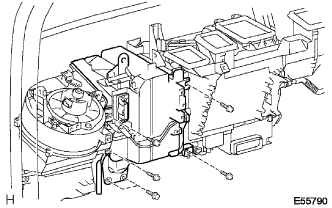
Remove the 3 bolts, nut and heater blower assembly front.
-