AIR CONDITIONING SYSTEM TERMINALS OF ECU

-
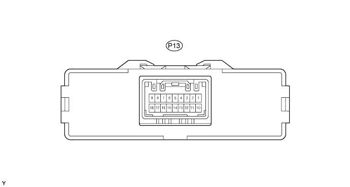
CHECK PTC HEATER AMPLIFIER ASSEMBLY (w/ PTC Heater)
-
Disconnect the P13 PTC heater amplifier connector.
-
Measure the voltage and resistance of the wire harness side connector.
Symbols (Terminal NO.) Wiring Color Terminal Description Condition Specified Condition IG (P13-1) - GND (P13-15) R-B - W-B Power source (IG) Ignition switch OFF Below 1 V IG (P13-1) - GND (P13-15) R-B - W-B Power source (IG) Ignition switch ON 11 to 14 V GND (P13-15) - Body ground W-B - Body ground Ground Always Below 1 Ω BLW (P13-2) - GND (P13-15) W - W-B Temperature control switch signal Temperature control knob: Max HOT Below 1 Ω BLW (P13-2) - GND (P13-15) W - W-B Temperature control switch signal Temperature control knob: except Max HOT 10 kΩ or higher HLS (P13-10) - GND (P13-15) R-W - W-B Light control switch signal Light control switch ON Below 1 V HLS (P13-10) - GND (P13-15) R-W - W-B Light control switch signal Light control switch OFF 11 to 14 V
-
If the result is not as specified, there may be a malfunction on the wire harness side.
-
-
Reconnect the P13 PTC heater amplifier connector.
-
Measure the voltage of the wire harness side connector.
Symbols (Terminal NO.) Wiring Color Terminal Description Condition Specified Condition BLW (P13-2) - GND (P13-15) W - W-B Temperature control switch signal Ignition switch ON
Temperature control knob: Max HOT
Blower switch ON
11 to 14 V BLW (P13-2) - GND (P13-15) W - W-B Temperature control switch signal Ignition switch ON
Temperature control knob: except Max HOT
Blower switch ON
Below 1 V HEAT (P13-13) - GND (P13-15) Y-B - W-B Idle-up switch input signal Ignition switch ON
Idle-up switch ON (momentary switch)
Below 1 V HEAT (P13-13) - GND (P13-15) Y-B - W-B Idle-up switch input signal Ignition switch ON
Idle-up switch OFF (momentary switch)
11 to 14 V IND (P13-8) - GND (P13-15) W-L - W-B Heater switch indicator light signal Ignition switch ON
Idle-up switch ON (momentary switch)
11 to 14 V IND (P13-8) - GND (P13-15) W-L - W-B Heater switch indicator light signal Ignition switch ON
Idle-up switch OFF (momentary switch)
Below 1 V TW (P13-4) - GND (P13-15) R - W-B Water temperature signal Ignition switch ON Pulse generation TACO (P13-11) - GND (P13-15) B - W-B Tachometer signal Engine running Pulse generation
(see waveform 1)
ALT (P13-14) - GND (P13-15) L - W-B Generator Engine running Pulse generation PTC1 (P13-6) - GND (P13-15) L-W - W-B PTC heater relay signal Ignition switch ON
Temperature control knob: Max HOT
Blower switch ON
Coolant temperature: 65°C (149°F) or lower
Engine revolution: 650 rpm or more
Generator: Generation signal output
11 to 14 V PTC1 (P13-6) - GND (P13-15) L-W - W-B PTC heater relay signal Ignition switch ON
Temperature control knob: except Max HOT
Blower switch OFF
Coolant temperature: 65°C (149°F) or lower
Below 1 V PTC2 (P13-7) - GND (P13-15) W - W-B PTC heater relay signal Ignition switch ON
Temperature control knob: Max HOT
Blower switch ON
Coolant temperature: 65°C (149°F) or lower
Engine revolution: 650 rpm or more
Generator: Generation signal output
11 to 14 V PTC2 (P13-7) - GND (P13-15) W - W-B PTC heater relay signal Ignition switch ON
Heater switch OFF
Temperature control knob: except Max HOT
Blower switch OFF
Coolant temperature: 65°C (149°F) or lower
Below 1 V PTCR (P13-5) - GND (P13-15) W-R - W-B Heater switch output signal for idle-up Ignition switch ON
Blower switch ON
Power heater switch ON
Temperature control knob: Max HOT
Below 1 V PTCR (P13-5) - GND (P13-15) W-R - W-B Heater switch output signal for idle-up Ignition switch ON
Blower switch OFF
Power heater switch OFF
Temperature control knob: Max HOT
11 to 14 V If the result is not as specified, the heater amplifier may have a malfunction.
-
Inspect using an oscilloscope.
-
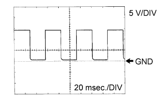
Waveform 1
Item Content Symbols (Terminal No.) TACO (P13-11) - GND (P13-15) Tool Setting 5 V/DIV., 20 msec./DIV. Condition Engine idling Tech Tips
As engine speed increases, the wavelength shortens.
-
-
-
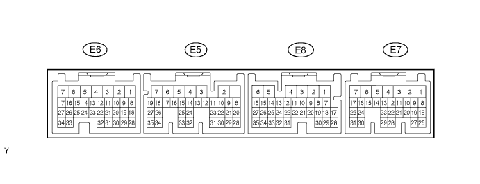
CHECK ECM
-
Measure the voltage of the connectors.
-
1KD-FTV
w/ PTC heater Symbols (Terminal NO.) Wiring color Terminal Description Condition Specified Condition HSW (E8-16) - E01 (E6-7) W-R - BR Heater switch output signal for idle-up Ignition switch ON
Blower switch ON
Power heater switch ON
Temperature control knob: Max HOT
Below 1 V HSW (E8-16) - E01 (E6-7) W-R - BR Heater switch output signal for idle-up Ignition switch ON
Blower switch OFF
Power heater switch OFF
Temperature control knob: Max HOT
11 to 14 V THWO (E7-2) - E01 (E6-7) R -BR *1
R-L -BR *2
Engine coolant temperature signal Ignition switch ON Pulse generation TACH (E7-4) - E01 (E6-7) B - BR Tachometer signal Engine running Pulse generation
(see waveform 1)
*1: Europe
*2: Singapore
-
If the result is not as specified, the ECM may have a malfunction.
-
-
-

Inspect using an oscilloscope.
-
Waveform 1
Item Content Symbols (Terminal No.) TACH (E7-4) - E01 (E6-7) Tool Setting 5 V/DIV., 20 msec./DIV. Condition Engine idling Tech Tips
As engine speed increases, the wavelength shortens.
-
-