POWER STEERING LINK REASSEMBLY

-
INSTALL OIL SEAL
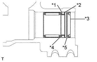
Text in Illustration *1 O-ring *2 Ring *3 Oil Seal *4 Snap Ring *5 Spacer
-
Coat new the spacer and O-ring, ring with power steering fluid.
-
Install the O-ring, spacer and ring.
-
Using a snap ring pliers, install a new snap ring.
-
Coat new oil seal with power steering fluid.
-
Install oil seal to the gear housing.
-
-
INSTALL O-RING
-
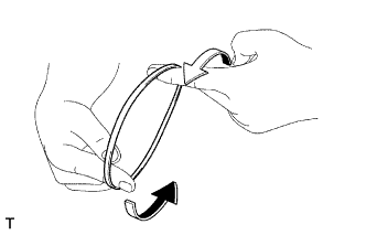
Coat a power piston, dust seal and a new O-ring with power steering fluid.
-
Snug the dust seal down with the piston ring compressor for 5 - 7 minutes.
-
-
INSTALL VALVE HOUSING ASSEMBLY
-
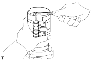
Using a plastic hammer and a sliding handle, lightly tap in 2 new union seat.
Note
Before installing the union seat, remove dust sticking to the control valve housing.
-
Mount the gear housing on SST and clamp SST in a vise.
-
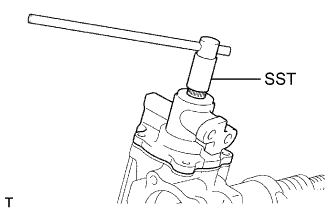
Using SST, install the power piston assembly unit holding the power piston by your finger.
- SST
- 09616-00011
-
Install the 4 bolts.
- Torque:
- 46 N*m { 470 kgf*cm, 34 ft.*lbf }
-
-
INSPECT PRELOAD
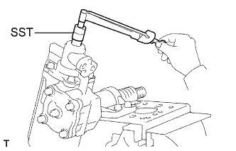
-
Using SST, check the power piston rotating torque.
- SST
- 09616-00011
Rotating torque 0.29 - 0.54 N*m (3.0 - 5.51 kgf*cm, 2.58 - 4.75 in.*lbf) If the rotating torque is not within the limits or the difference between clockwise and counterclockwise rotating torque is over 0.54 N*m (5.51 kgf*cm, 4.75 in.*lbf), replace the power steering gear assembly.
-
-
INSTALL SIDE COVER
-
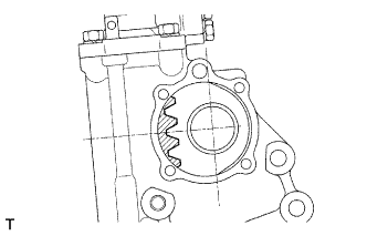
Set the power piston at the center of the shaft.
-
To prevent oil seal and O-ring from damage, wind vinyl tape on the serrated part of the sector shaft.
-
Install and push the sector shaft into the gear housing so that the center teeth mesh together.
-
Install the sector shaft side cover with the 4 bolts.
- Torque:
- 46 N*m { 470 kgf*cm, 34 ft.*lbf }
-
-
INSPECT TOTAL PRELOAD
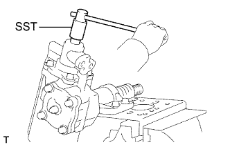
-
Using SST, turn the power piston shaft to full lock in both direction and determine the exact center.
- SST
- 09616-00011
-
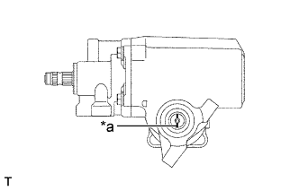
Text in Illustration *a Matchmark Align the matchmarks on the power piston shaft and end cover of the power piston assembly to show neutral position.
-
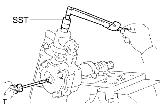
Install SST with a torque wrench in the power piston shaft.
- SST
- 09616-00011
-
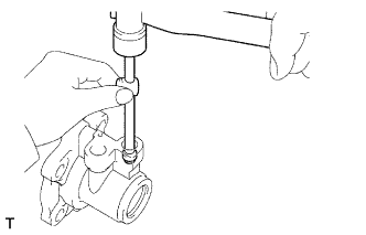
Using a screw driver, turn the sector shaft adjusting screw until the preload is within specification.
Preload (turning) 0.49 - 0.93 N*m (5.0 - 9.5 kgf*cm, 4.3 - 8.2 in.*lbf) -
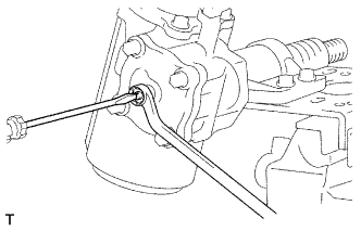
Using a screw driver, hold the adjusting screw and torque the lock nut.
- Torque:
- 46 N*m { 469 kgf*cm, 33 ft.*lbf }
-
Recheck the total preload.
Preload (turning) 0.49 - 0.93 N*m (5.0 - 9.5 kgf*cm, 4.3 - 8.2 in.*lbf)
-