POWER STEERING LINK INSTALLATION

-
INSTALL STEERING KNUCKLE ARM LH
-
Install the woodruff key to the knuckle arm.
-
Install the knuckle arm to the steering knuckle.
-
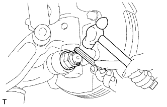
Using a socket wrench (32 mm), tighten the new lock nut.
-
Using a hammer and a chisel, stake the lock nut.
-
-
INSTALL STEERING KNUCKLE ARM RH
Tech Tips
Install the RH side by the same procedures with the LH side.
-
INSTALL TIE ROD END SUB-ASSEMBLY LH
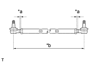
Text in Illustration *a 6.5 mm (0.3 in) *b 1163 mm (45.8 in)
-
Screw the lock nuts and tie rod ends into the tie rod.
Tech Tips
The tie rod length should be approximately 1163 mm (45.8 in.), and the remaining length of threads on both tie rods should be equal.
-
-
INSTALL TIE ROD END SUB-ASSEMBLY RH
Tech Tips
Install the RH side by the same procedures with the LH side.
-
INSTALL STEERING TIE ROD
-
Install the tie rod to the right and left knuckle arm, then install and tighten 2 nuts.
- Torque:
- 91 N*m { 928 kgf*cm, 67 ft.*lbf }
-
-
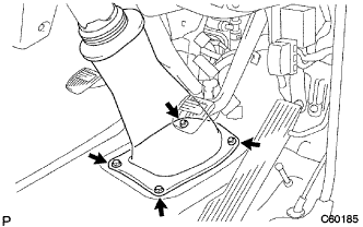
INSTALL POWER STEERING GEAR ASSEMBLY
-
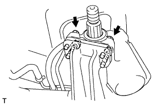
Install the power steering gear with the 4 bolts and washers.
- Torque:
- 140 N*m { 1430 kgf*cm, 103 ft.*lbf }
-
-
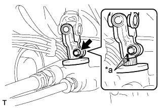
INSTALL PITMAN ARM
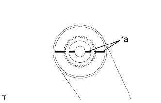
Text in Illustration *a Matchmark
-
Align the alignment marks on the sector shaft and the pitman arm.
-
Install the spring washer and nut.
- Torque:
- 175 N*m { 1785 kgf*cm, 129 ft.*lbf }
-
-
INSTALL STEERING DRAG LINK ASSEMBLY
-
Install the drag link to the knuckle arm and steering knuckle, then install and tighten the 2 nuts.
- Torque:
- 150 N*m { 1530 kgf*cm, 110 ft.*lbf }
-
Install the new 2 cotter pins.
-
-
INSTALL STEERING GEAR OUTLET RETURN TUBE
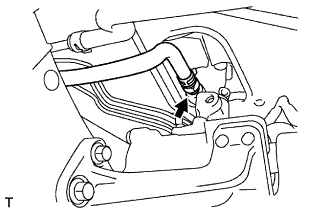
-
Using a union nut wrench, connect the return tube.
- Torque:
- 40 N*m { 408 kgf*cm, 30 ft.*lbf, for use with union nut wrench }
Tech Tips
-
Use a torque wrench with a fulcrum length of 300 mm (11.81 in.).
-
This torque value is effective in case that a union nut wrench is parallel to a torque wrench.
-
Install the return hose with the clip.
-
-
INSTALL PRESSURE FEED TUBE ASSEMBLY
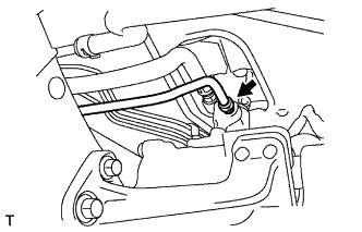
-
Using a union nut wrench, connect the pressure feed tube.
- Torque:
- 40 N*m { 408 kgf*cm, 30 ft.*lbf, for use with union nut wrench }
Tech Tips
-
Use a torque wrench with a fulcrum length of 300 mm (11.81 in.).
-
This torque value is effective in case that a union nut wrench is parallel to a torque wrench.
-
-
INSTALL STEERING SLIDING W/COUPLING YOKE SUB-ASSEMBLY
-
Align the matchmarks on the steering intermediate shaft and power steering gear assembly.
Text in Illustration *a Matchmark -
Install the bolt.
- Torque:
- 35 N*m { 357 kgf*cm, 26 ft.*lbf }
-
Install the 4 bolts and steering column tube lower.
- Torque:
- 8.0 N*m { 82 kgf*cm, 71 in.*lbf }
-
-
PLACE FRONT WHEELS FACING STRAIGHT AHEAD
-
INSTALL TURN SIGNAL SWITCH ASSEMBLY (W/ SRS AIRBAG)
-
INSTALL SPIRAL CABLE SUB-ASSEMBLY (W/ SRS AIRBAG)
-
INSTALL STEERING COLUMN COVER LWR (W/ SRS AIRBAG)
-
CENTER SPIRAL CABLE (W/ SRS AIRBAG)
-
Check that the ignition switch is OFF.
-
Check that the battery negative terminal is disconnected.
Note
Do not start the operation for 90 seconds after removing the terminal.
-
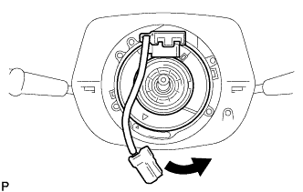
Turn the cable counterclockwise by hand until it becomes harder to turn.
Tech Tips
The cable will rotate about 3.5 turns to either left or right of the center.
-
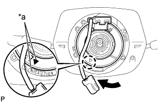
Text in Illustration *a Matchmarks Then rotate the cable clockwise about 3.5 turns to align the marks.
-
-
INSTALL STEERING WHEEL ASSEMBLY (W/ SRS AIRBAG)
-
INSPECT STEERING WHEEL CENTER POINT (W/ SRS AIRBAG)
-
INSTALL HORN BUTTON ASSEMBLY (W/ SRS AIRBAG)
-
INSPECT HORN BUTTON ASSEMBLY (W/ SRS AIRBAG)
-
INSTALL FRONT WHEEL
- Torque:
- 14 inch
- 135 N*m { 1377 kgf*cm, 100 ft.*lbf }
- 15 inch
- 170 N*m { 1734 kgf*cm, 125 ft.*lbf }
-
BLEED POWER STEERING FLUID
-
Check the fluid level.
-
Jack up the front of the vehicle and support it with stands.
-
Turn the steering wheel.
-
With the engine stopped, turn the wheel slowly from lock to lock several times.
-
-
Lower the vehicle.
-
Start the engine.
-
Run the engine at idle for a few minutes.
-
-
Turn the steering wheel.
-
With the engine idling, turn the wheel to the left or right full lock position and keep it there for 2 - 3 seconds. Then turn the wheel to the opposite full lock position and keep it there for 2 - 3 seconds (step A).
-
Repeat step A several times.
-
-
Stop the engine.
-
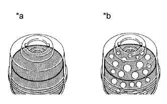
Text in Illustration *a Normal *b Abnormal Check for foaming or emulsification.
Especially, if the system has to be bled twice because of foaming or emulsification, check for fluid leakage in the system.
-
Check the fluid level.
-
-
CHECK POWER STEERING FLUID LEAKAGE
-
INSPECT SRS WARNING LIGHT (W/ SRS AIRBAG)
-
INSTALL HEADLAMP UNIT ASSEMBLY LH (LHD STEERING POSITION TYPE)
-
INSTALL HEADLAMP UNIT ASSEMBLY RH (RHD STEERING POSITION TYPE)
-
INSPECT AND ADJUST FRONT WHEEL ALIGNMENT
-
HEADLIGHT AIM ONLY