POWER STEERING LINK DISASSEMBLY

-
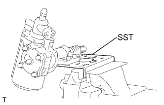
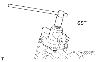
FIX POWER STEERING GEAR ASSEMBLY
-
Mount the gear housing on SST and clamp SST in a vise.
- SST
- 09630-00014 ( 09631-00142 )
-
-
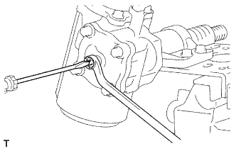
REMOVE SIDE COVER
-
Using a screwdriver, remove the sector shaft adjusting screw lock nut.
-
Remove the 4 bolts.
-
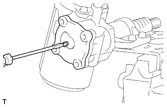
Using a screwdriver, turn the sector shaft adjusting screw clockwise until the cover comes off.
-
Remove the O-ring from the side cover.
-
-
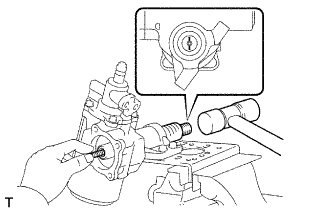
REMOVE SECTOR SHAFT
-
Using a plastic hammer, tap on the sector shaft end, and pull out the sector shaft, as shown in the illustration.
-
-
REMOVE VALVE HOUSING ASSEMBLY
-
Remove the 4 bolts.
-
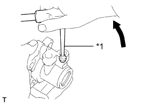
Using SST, turn the power piston shaft clockwise until the shaft is locked. Then turn the power piston shaft counterclockwise until the end cover of the power piston assembly is separated from the gear housing by holding the power piston with your finger.
- SST
- 09616-00011
-
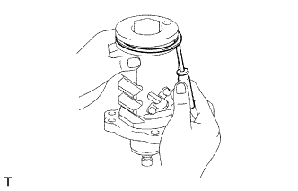
While holding the power piston, pull out the power piston sub-assembly.
-
Text in Illustration *1 Screw Extractor Using a screw extractor, remove the 2 union seat from the valve housing.
-
-
REMOVE O-RING
-
Using a screwdriver, remove the dust seal and O-ring from the power piston assembly.
Note
Be careful not to damage the power piston subassembly.
-
-
REMOVE OIL SEAL
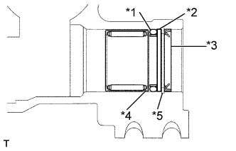
Text in Illustration *1 O-ring *2 Ring *3 Oil Seal *4 Spacer *5 Snap Ring
-
Using a screwdriver, remove the oil seal from the gear housing.
-
Using a snap ring pliers, remove the snap ring.
-
Remove the ring, spacer and O-ring
-
-
INSPECT SECTOR SHAFT

Text in Illustration *1 Dial Indicator
-
Using a dial indicator, measure the thrust clearance.
Maximum clearance 0.03 - 0.05 mm (0.0012 - 0.0020 in.)
-