AIRBAG SYSTEM PRECAUTION

Tech Tips
-
In this section, the No. 2 airbag sensor assembly and airbag ECU assembly are collectively referred to as the airbag sensors.
-
The horn button assembly and front seat outer belt assembly are collectively referred to as the Supplemental Restraint System (SRS) parts.
-
PRECAUTIONS FOR HANDLING OF SRS
-
Failure to carry out service operations in the correct sequence could cause the SRS to deploy unexpectedly during servicing, and this could lead to a serious accident. Furthermore, if a mistake is made when servicing the SRS, it is possible that it may fail to deploy when required.
-
Before performing servicing (including the removal, installation, inspection, and replacement of parts), be sure to read and follow the precautions and procedures described below.
-
-
PRECAUTIONS FOR DISCONNECTION OF CABLE FROM NEGATIVE BATTERY TERMINAL
-
Before beginning troubleshooting, check for DTCs, and turn the ignition switch off. Then disconnect the cable from the negative (-) battery terminal, and wait at least 90 seconds.
-
The SRS is equipped with a backup power source, so if work is begun within 90 seconds of the cable being disconnected from the negative (-) battery terminal, the SRS may be deployed.
-
-
GENERAL PRECAUTIONS
-
Be sure to use the Toyota electrical tester for electrical inspections.
-
Follow the cautions on the labels attached to each part of the system.
-
To prevent accidental deployment of the SRS parts due to static electricity, be sure to touch a metal surface with your bare hands to discharge static electricity before performing servicing operation on the SRS.
-
Never disassemble any of the SRS parts or airbag sensors.
-
If any of the SRS parts or airbag sensors are dropped, or if any cracks, dents or other defects are found in them, replace them with new ones.
-
Never use SRS parts that have been removed from another vehicle. When replacing SRS parts, replace them with new ones.
-
Do not expose SRS parts directly to hot air or flames.
-
Be sure to inspect the SRS parts, even in the case of a minor collision where they have not been deployed.
-
Do not apply grease, detergent, oil or water to the SRS parts.
-
When servicing or storing SRS parts, avoid places where the temperature and humidity are high, and keep the parts away from electrical noise.
-
Never measure the resistance of the SRS parts using an electrical tester.
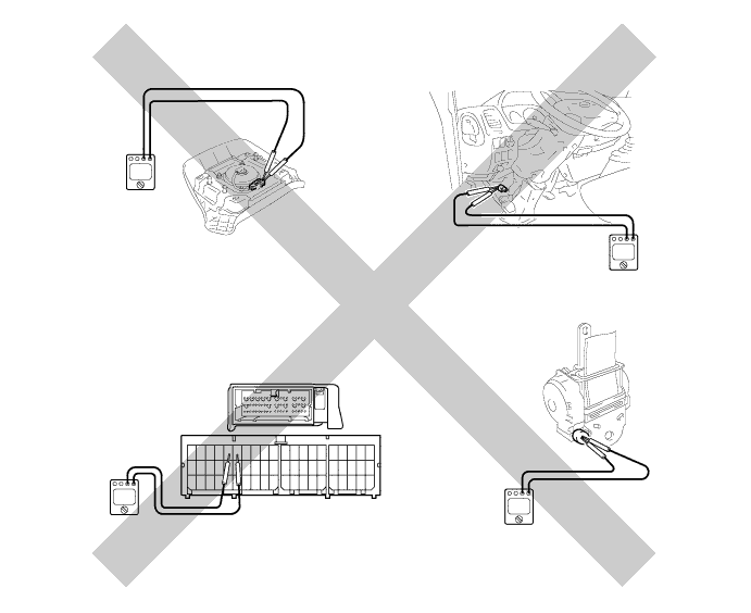
CAUTION:
Never measure the resistance of the SRS parts using an electrical tester. The electrical current from the electrical tester may cause the deployment of the SRS parts, and this could lead to a serious injury.
-
Before scrapping a vehicle equipped with SRS, or disposing of a single airbag or pretensioner, be sure to deploy the SRS parts using SST.
Tech Tips
-
Disposal of the horn button assembly Click here
-
Disposal of the front seat outer belt assembly Click here
-
-
-
PRECAUTIONS FOR DISPOSAL OF UNDEPLOYED SRS PARTS
CAUTION:
Before performing the pre-disposal deployment of SRS components, review and closely follow all applicable environmental and hazardous material regulations. Pre-disposal deployment may be considered hazardous material treatment.
-
Never dispose of SRS parts that have not been deployed.
-
Be sure to perform the deployment operation in a safe, flat place outdoors. Select a location where nearby residents will not be disturbed.
-
As the deployment operation creates a loud noise, be sure to inform nearby residents before performing the operation.
-
When deploying the SRS parts, always use SST and perform the operation at least 10 m (32.8 ft.) away from the SRS parts.
-
To prevent the accidental deployment of the SRS parts due to static electricity, be sure to touch a metal surface with your bare hands to discharge static electricity before performing this procedure.
-
Do not face the airbag deployment side downwards when activating the SRS parts.
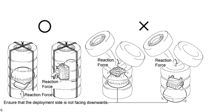
CAUTION:
Be aware of the deployment force and direction when deploying the SRS parts. It is possible that forces of more than 9800N (999 kgf, 2203 lbf) could be applied in the directions indicated by the arrows in the illustration.
-
-
PRECAUTIONS FOR DISPOSAL OF DEPLOYED SRS PARTS
-
Since the SRS parts become extremely hot when they are deployed, do not touch them for at least 30 minutes after deployment.
-
Never apply water, etc. to deployed SRS parts.
-
Use gloves and safety glasses when handling deployed SRS parts.
-
Place the deployed SRS parts in a thick, clear plastic bag and seal it before disposing of them.
-
Always wash your hands with water after completing the operation.
-
-
WHEN SERVICING A DAMAGED VEHICLE
-
Before using a welder on the vehicle, be sure to remove the SRS parts.
-
If shocks are likely to be applied to any of the airbag sensors, remove them before the operation.
-
Never expose the airbag sensors directly to hot air.
-
-
SITUATIONS WHERE SRS INSPECTION IS NECESSARY
-
When the vehicle has been involved in a collision, regardless of whether the SRS deployed or not
-
When the SRS warning light indicates abnormality
-
When SRS-related DTCs are indicated
-
-
PRECAUTIONS FOR AIRBAG
-
Keep the deployment side of the airbag facing upwards, even when it is removed temporarily during an operation.
CAUTION:
Never place an airbag with its deployment side facing downwards. If the airbag deploys unexpectedly during servicing, with its deployment side facing downwards, it may bounce around and this could lead to a serious injury.
-
When storing airbags, do not put anything on top of them or pile them one on top of the other.
-
-
PRECAUTIONS FOR FRONT SEAT OUTER BELT ASSEMBLY WITH PRETENSIONER
-
Never touch the areas where the retractors are installed, even when the pretensioner is temporarily removed.
CAUTION:
Never touch the areas where the retractors are installed. If a retractor and its pretensioner deploys unexpectedly during servicing, the seat belt could retract, and this could lead to a serious injury.
-
When storing pretensioners, do not put anything on top of them or pile them one on top of the other.
-
-
PRECAUTIONS FOR SPIRAL CABLE
-
Be sure to center the spiral cable sub-assembly when installing the spiral cable, and when installing and removing the steering wheel Click here.
CAUTION:
Confirm that the spiral cable sub-assembly is centered when it is installed. If the steering wheel is turned and the spiral cable subassembly is not centered, the cable may break.
-
-
PRECAUTIONS FOR AIRBAG SENSORS
-
When any of the SRS parts have been deployed in a collision, be sure to replace all of the airbag sensors (airbag ECU assembly and No. 2 airbag sensor assembly) as a set.
-
When connecting or disconnecting the connector of an airbag sensor, ensure that the sensor is installed into the vehicle securely.
-
-
PRECAUTIONS FOR WIRE HARNESSES AND CONNECTORS
-
All the wire harnesses for the SRS, except the unexposed harnesses in the engine compartment, are colored yellow.
-
As the connectors used in the SRS are specially-designed, be careful when handling them. For details, refer to the following.
-
-
FEATURES OF CONNECTORS USED IN SRS
-
All the connectors in the SRS, except certain specified connectors, are colored yellow to distinguish them from other connectors. Some connectors have special functions, and are specially designed for the SRS. These connectors use durable gold-plated terminals, and are placed in the locations shown in the illustration.
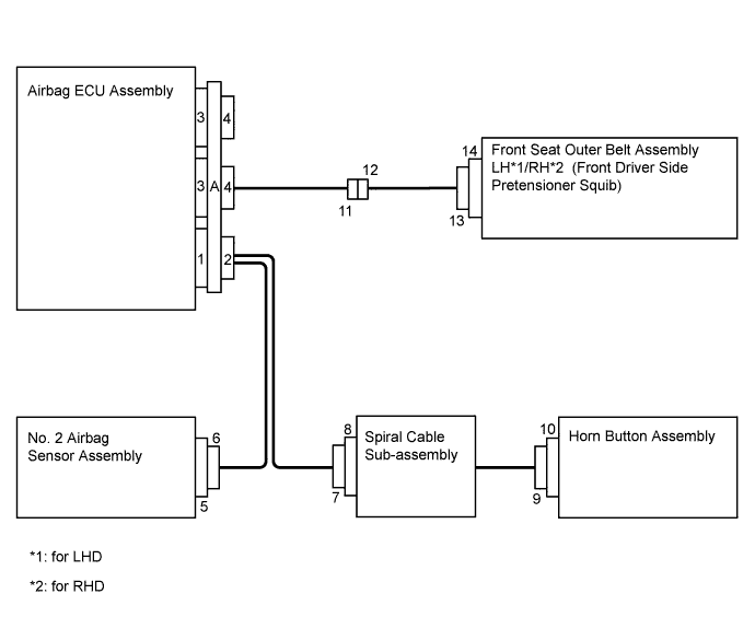
Feature Application Terminal Twin-Lock Mechanism Connectors 2, 4, 6, 7, 8, 9, 10, 11, 12 Half Connection Prevention Mechanism Connectors 6, 7, 9, 12 Connector Lock Mechanism Connector A Improper Connection Prevention Lock Mechanism Connector A Activation Prevention Mechanism Connectors 2, 4, 8, 10, 14 -
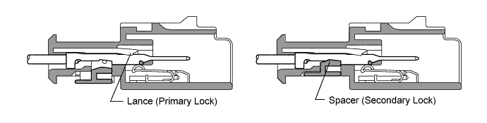
Terminal twin-lock mechanism
-
This mechanism is designed to increase the capability of retaining the terminal in the housing.
-
The connector has a two-piece structure, consisting of the housing and the spacer, to lock the terminal securely, using both the lance (primary lock) and the spacer (secondary lock).
-
-
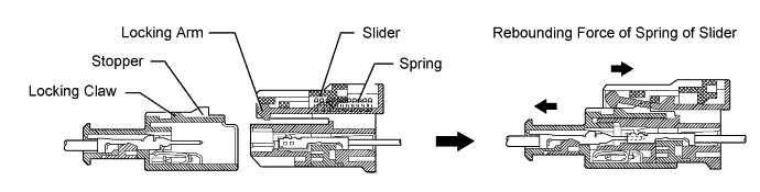
Half connection prevention mechanism
-
This mechanism is designed to prevent the improper connection of the connector.
-
If the connector is not fully inserted, the spring pushes it back, and it cannot be engaged. This makes it easy to confirm the connection status of the connector.
-
Once the connector has been fully inserted, the spring pushes the slider so that the locking arm can engage to the locking claw securely.
Tech Tips
The above illustration shows an example of the half connection prevention mechanism.
-
-
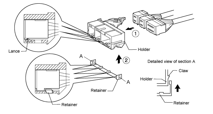
Connector lock mechanism
-
This mechanism is designed to prevent the connector from accidentally being disconnected.
-
When the connector is installed into the holder fully, the lance of the holder retains the connector as the primary lock.
-
After all the connectors have been inserted into the holder, the retainer is installed into the holder as the secondary lock.
-
-
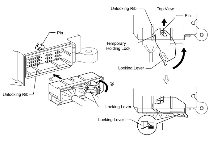
Improper connection prevention lock mechanism
-
This mechanism is designed to prevent the improper connection of the connectors.
-
When the holder is connected to the airbag ECU assembly, the unlocking rib unlocks the temporary holding lock, allowing the locking lever to be turned in the direction indicated by the arrow in the illustration.
-
The crab claws on the other side of the locking lever catch the pin, and the holder moves in the engaging direction while the locking lever is turned in the direction indicated by the arrow in the illustration.
-
When the locking lever has been turned as far as it will go, the holder is fully inserted and the locking lever is locked so that the holder is secured in position.
-
-
Activation prevention mechanism
-
This mechanism is designed to prevent the accidental deployment of SRS parts during service operations.
-
An activation prevention mechanism is built into the connectors of the squib circuit.
-
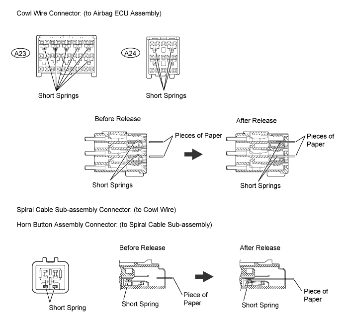
When the connectors with this mechanism are disconnected, the short spring comes into contact with the terminals and closes the squib circuit so that the external electric current does not flow into the squib.
-
-
Releasing method of activation prevention mechanism
-
To release the activation prevention mechanism, insert a piece of paper of the same thickness as the engaging parts (approximately 0.5 mm (0.020 in.)) between the terminal and the short spring to break the contact.
-
Refer to the illustration shown below, regarding connectors with activation prevention mechanisms and the method for releasing the mechanism.
CAUTION:
Never release the activation prevention mechanism of the squib circuit connector unless otherwise specified, even when the connector is disconnected.
Note
-
Never release the activation prevention mechanism unless specifically directed to do so in a troubleshooting procedure.
-
To prevent the terminal and the short spring from being damaged, always use a piece of paper of the same thickness as the engaging parts.
-
-
-
-
DISCONNECTION/CONNECTION OF CONNECTORS FROM/TO AIRBAG ECU ASSEMBLY
-
Disconnection procedure
-
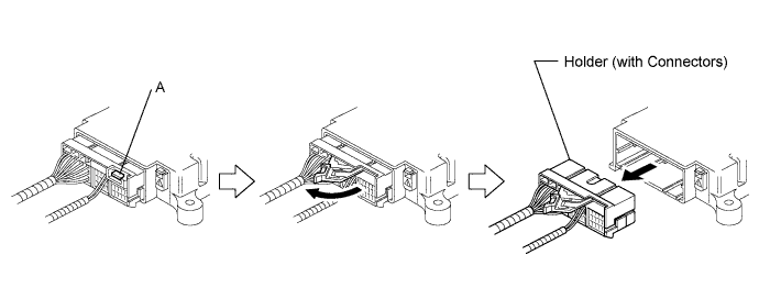
Pull the locking lever out by pushing the part indicated with an "A" in the illustration.
-
Turn the locking lever in the direction indicated by the arrow in the illustration.
-
Disconnect the holder.
-
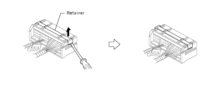
Remove the retainer using a screwdriver (if the connectors need to be removed).
-
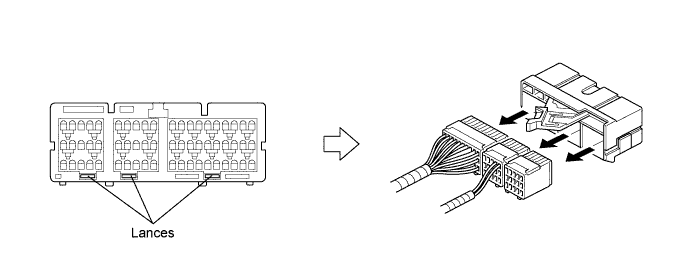
Remove the connectors by releasing the lances (if the connectors need to be removed).
-
-
Connection procedure
-
Insert the connectors into the holder until the lances lock them (if the connectors are disconnected).
-
Install the retainer (if the connectors are disconnected).
-
Insert the holder into the connector of the airbag ECU assembly until it can not be pushed in any further.
-
Push and rotate the locking lever until it is locked to the holder. (A "click" sound will be heard.)
-
-
-
DISCONNECTION/CONNECTION OF CONNECTORS FROM/TO NO. 2 AIRBAG SENSOR ASSEMBLY
-
Disconnection procedure
-
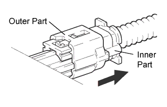
Hold both sides of the outer part.
-
Pull the outer part out in the direction indicated by the arrow in the illustration.
-
When the lock has been released, the connector can be disconnected.
-
-
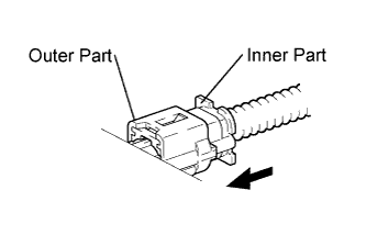
Connection procedure
-
Hold the inner part.
-
Connect the connectors by moving them in the direction indicated by the arrow in the illustration.
-
While inserting the connector further by pushing the inner part, the outer part will move and lock the connector automatically. (A "click" sound will be heard.)
-
-
-
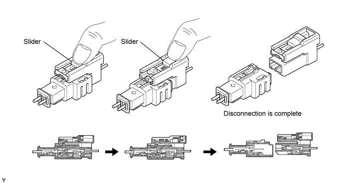
DISCONNECTION/CONNECTION OF OTHER CONNECTORS
Applicable connectors are:
-
Connector to the horn button assembly
-
Connector to the spiral cable sub-assembly
-
Connector for connecting the cowl wire and the floor wire
-
Disconnection procedure
-
Slide the slider so that the locking arm can be disengaged from the locking claw.
-
Disconnect the connector.
-
-
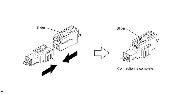
Connection procedure
-
Move the connectors in the directions indicated by the arrows in the illustration to connect them.
-
Confirm that the locking arm is engaged with the locking claw, and that they are covered by the slider. (A "click" sound will be heard.)
-
-