TEMPERATURE CONTROL SWITCH INSTALLATION

-
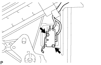
INSTALL TEMPERATURE CONTROL SWITCH ASSEMBLY
-
Install the temperature control switch with the 2 screws.
-
-
INSTALL AIR MIX DAMPER CONTROL CABLE SUB-ASSEMBLY
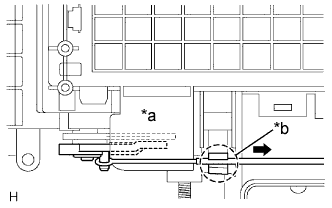
Text in Illustration *a COOL *b Clamp
-
Connect the heater control cable to the heater control, with the lever in the MAX COOL position.
-
Connect the inner cable to the control lever in MAX COOL position.
-
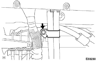
Connect the outer cable to the clamp while slightly pulling it to the direction shown by arrow in the illustration.
Note
When operating the mode control lever, check that it remains in position at both ends of MAX COOL and MAX HOT, and no rebound occurs.
-
-
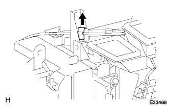
INSTALL HEATER CONTROL CABLE SUB-ASSEMBLY

Text in Illustration *a DEF
-
Connect the heater control cable to the heater control with the lever in the DEF position.
-
Connect the inner cable to the control lever in DEF position.
-
Connect the outer cable to the clamp while slightly pulling it to the direction shown by arrow in the illustration.
Note
When operating the mode control lever, check that it remains in position at both ends of FACE and DEF, and no rebound occurs.
-
-
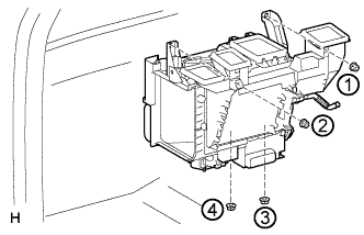
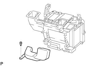
INSTALL HEATER RADIATOR ASSEMBLY
-
Install the heater radiator with the 4 nuts.
Tech Tips
Tighten the bolts in the sequence order shown in the illustration to install the heater radiator.
-
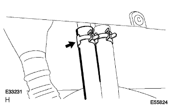
Connect the outer cable to the clamp.
-
Connect the connector and engage the 2 claws.
-
-
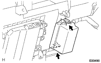
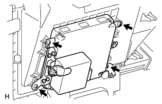
INSTALL ECM (for 1KD-FTV, 2KD-FTV)
-
Install the ECM with the 4 screws.
-
-
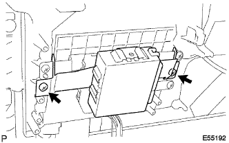
INSTALL SKID CONTROL ECU ASSEMBLY
-
Install the skid control ECU with the 2 screws.
-
-
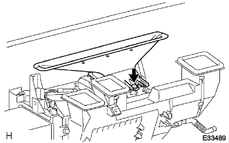
INSTALL LOWER DEFROSTER NOZZLE ASSEMBLY
-
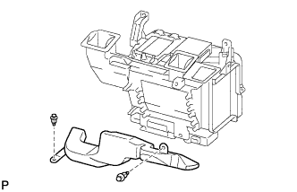
Install the lower defroster nozzle with the screw.
-
-
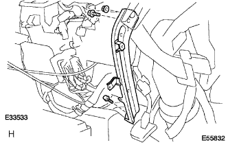
INSTALL NO. 1 AIR DUCT SUB-ASSEMBLY

-
Install the air duct with the 3 bolts and 4 screws.
Tech Tips
Tighten the bolts in the sequence order shown in the illustration to install the air duct.
-
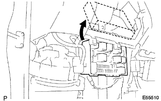
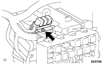
Connect the relay block.
-
Install the bolt.
-
Connect the blower resistor connector.
-
Install the relay block with the screw.
-
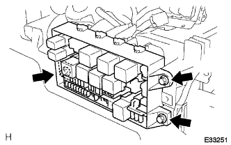
Install the relay block with the 3 bolts.
-
-
INSTALL WINDSHIELD WASHER JAR ASSEMBLY
-
Connect the hose and connector to the washer pump.
-
Install the windshield washier jar with the 2 bolts.
-
-
INSTALL INSTRUMENT PANEL REINFORCEMENT
-
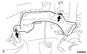
Install the instrument panel reinforcement with the 2 bolts and 4 nuts.
-
-
INSTALL STEERING COLUMN LOWER TUBE ASSEMBLY
-
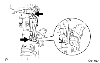
Install the steering column lower tube with the 2 bolts and 2 nuts.
-
-
INSTALL STEERING COLUMN ASSEMBLY
-
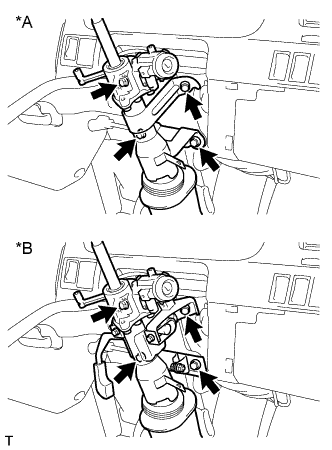
Install the 4 bolts and steering column assembly.
Text in Illustration *A Non-Tilt Steering Column *B Tilt Steering Column - Torque:
- 11.5 N*m { 117 kgf*cm, 9 ft.*lbf }
-
Install the 2 bolts and clamp bracket.
-
-
INSTALL NO. 1 AIR DUCT
-
Install the air duct with the 2 clips.
-
-
INSTALL NO. 2 AIR DUCT (for LHD)
-
Install the air duct with the 2 clips (for Cold Area Specification Vehicles).
-
Install the air duct with the clip (except Cold Area Specification Vehicles).
-
-
INSTALL STEERING COLUMN LOWER COVER
-
Install the steering column cover LWR with the clip and 2 screws.
-
-
INSTALL STEERING COLUMN UPPER COVER
-
Install the steering column cover UPR with the 2 screws.
-
-
INSTALL FRONT DOOR SCUFF PLATE RH
-
INSTALL INSTRUMENT PANEL NO. 1 BRACE SUB-ASSEMBLY
-
Install the instrument panel brace with the 2 bolts and nut.
-
-
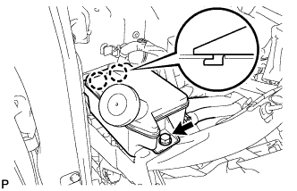
INSTALL BRAKE MASTER CYLINDER RESERVOIR SUB-ASSEMBLY
-
Install the brace master cylinder reservoir with the bolt.
-
-
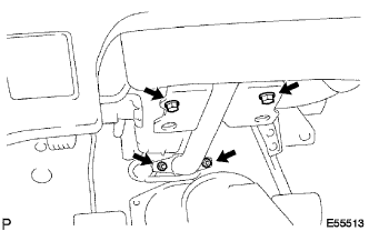
INSTALL INSTRUMENT PANEL SUB-ASSEMBLY
-
Remove the 2 clips.
-
Remove the 2 nuts<F> and 7 bolts<A><B>.
-
Disconnect the connectors and remove the instrument panel sub-assembly.
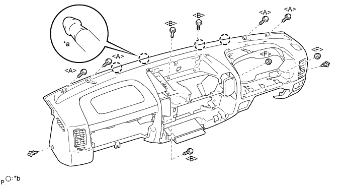
Text in Illustration *a Pin *b 4 Pins
-
-
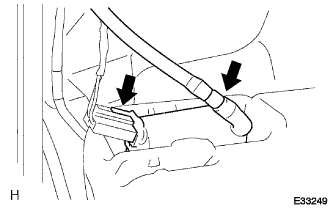
INSTALL HEATER WATER HOSE INLET B
-
Install the heater water inlet hose.
-
-
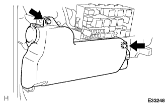
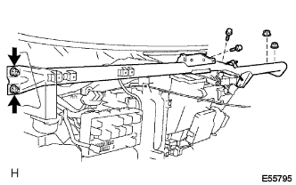
INSTALL HEATER WATER HOSE OUTLET B
-
Install the heater water outlet hose.
-
Install the heater bracket with the bolt.
-
-
INSTALL RADIATOR GRILLE
-
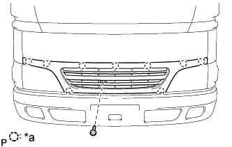
Text in Illustration *a Clip Remove the screw and 9 clips and radiator grille.
-
-
CONNECT CABLE TO NEGATIVE BATTERY TERMINAL
- Torque:
- 6.4 N*m { 65 kgf*cm, 56 in.*lbf }
-
ADD ENGINE COOLANT (for 1KD-FTV)
-
Pour coolant into the radiator until it overflows.
Capacity Specification Capacity w/o Heater 9.8 liters (10.3 US qts, 8.6 Imp. qts) w/ Front Heater 10.7 liters (11.3 US qts, 9.4 Imp. qts) w/ Front and Rear Heater 11.5 liters (12.2 US qts, 10.1 Imp. qts) Note
Do not substitute plain water for engine coolant.
Tech Tips
-
Use of improper coolants may damage the engine cooling system.
-
Use only Toyota Super Long Life Coolant or similar high quality ethylene glycol based non-silicate, non-amine, non-nitrite, and non-borate coolant with long-life hybrid organic acid technology (coolant with long-life hybrid organic acid technology consists of a combination of low phosphates and organic acids).
-
-
Check the coolant level inside the radiator by squeezing the inlet and outlet radiator hoses several times by hand.
If the coolant level goes down, add coolant.
-
Install the radiator cap securely.
-
Slowly pour coolant into the radiator reservoir until it reaches the FULL line.
-
Warm up the engine until the thermostat opens.
-
While the thermostat is open, circulate the coolant for several minutes.
Tech Tips
The thermostat open timing can be confirmed by pressing the inlet radiator hose by hand, and checking when the engine coolant starts to flow inside the hose.
-
-
Maintain the engine speed at 2000 to 2500 rpm.
-
Squeeze the inlet and outlet radiator hoses several times by hand while warming up the engine to bleed the air.
CAUTION:
-
Wear protective gloves.
-
Be careful as the radiator hoses are hot.
-
Keep your hands away from the fan.
When squeezing the radiator hoses:
-
-
Stop the engine and wait until the coolant cools down.
-
Remove the radiator cap and check the coolant level inside the radiator.
-
If the coolant level is below the full level, repeat the operation until the coolant level remains at the full level.
-
Check the coolant level inside the radiator reservoir tank again.
If it is below the full level, add coolant.
-
-
ADD ENGINE COOLANT (for 2KD-FTV)
-
Slowly fill the system with coolant.
-
Use of improper coolants may damage engine cooling system.
-
Use "Toyota Long Life Coolant" or equivalent and mix it with plan water according to the manufacturer's directions.
-
Using of coolant which includes more than 50 % [freezing protection down to -35°C (-31°F)] or 60 % [freezing protection down to -50°C (-58°F)] of ethylene-glycol is recommended but not more than 70 %.
Note
-
Do not use an alcohol type coolant or plain water alone.
-
The coolant should be mixed with plain water (preferably demineralized water or distilled water).
Capacity: w/ Front heater
w/o heater
10.1 liters (10.5 US qts, 8.7 Imp. qts)
9.2 liters (9.51 US qts, 7.9 Imp. qts)
w/ Front and Rear
heater
10.9 liters (11.5 US qts, 8.9 Imp. qts)
-
-
Reinstall the radiator cap.
-
Start the engine, and bleed the cooling system.
-
Refill the radiator reservoir with coolant until it reaches the "full" line.
-
-
WARM UP ENGINE
-
INSPECT FOR COOLANT LEAK (for 1KD-FTV)
-
Remove the radiator cap.
CAUTION:
To avoid the danger of being burned, do not remove the radiator cap while the engine and radiator are still hot. Thermal expansion will cause hot engine coolant and steam to blow out from the radiator.
-
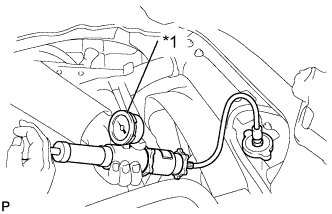
Text in Illustration *1 Radiator Cap Tester Fill the radiator with coolant and attach a radiator cap tester.
-
Warm up the engine.
-
Pump it to 118 kPa (1.2 kgf/cm2, 17.1 psi), then check that the pressure does not drop.
If the pressure drops, check the hoses, radiator and water pump for leakage. If there are no signs of external coolant leakage, check the heater core, cylinder block and head.
-
Reinstall the radiator cap.
-
-
INSPECT FOR COOLANT LEAK (for 2KD-FTV)
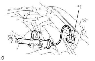
Text in Illustration *1 Radiator Cap Tester
-
Fill the radiator with coolant and attach a radiator cap tester.
-
Warm up the engine.
-
Pump it to 118 kPa (1.2 kgf/cm2, 17.1 psi), and check that the pressure does not drop.
If the pressure drops, check the hoses, radiator or water pump for leaks. If no external leaks are found, check the heater core, cylinder block and head.
-