POWER STEERING LINK REMOVAL

Tech Tips
COMPONENTS: Click here
-
REMOVE CLEARANCE LAMP LENS & BODY LH (LHD STEERING POSITION TYPE)
-
REMOVE CLEARANCE LAMP LENS & BODY RH (RHD STEERING POSITION TYPE)
-
REMOVE RADIATOR GRILLE
-
REMOVE HEADLAMP UNIT ASSEMBLY LH (LHD STEERING POSITION TYPE)
-
REMOVE HEADLAMP UNIT ASSEMBLY RH (RHD STEERING POSITION TYPE)
-
PRECAUTION (W/ SRS AIRBAG)
-
SEPARATE BATTERY NEGATIVE TERMINAL (W/ SRS AIRBAG)
-
PLACE FRONT WHEELS FACING STRAIGHT AHEAD
-
REMOVE HORN BUTTON ASSEMBLY (W/ SRS AIRBAG)
-
REMOVE STEERING WHEEL ASSEMBLY (W/ SRS AIRBAG)
-
Remove the steering wheel assembly set nut.
-
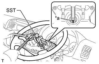
Text in Illustration *a Matchmark Place matchmarks on the steering wheel assembly and main shaft assembly.
-
Using SST, remove the steering wheel assembly.
- SST
- 09950-50013 ( 09951-05010, 09952-05010, 09953-05010, 09954-05021 )
-
-
REMOVE STEERING COLUMN COVER LWR (W/ SRS AIRBAG)
-
REMOVE TURN SIGNAL SWITCH ASSEMBLY (W/ SRS AIRBAG)
-
REMOVE SPIRAL CABLE SUB-ASSEMBLY (W/ SRS AIRBAG)
-
SEPARATE STEERING SLIDING W/COUPLING YOKE SUB-ASSEMBLY
-
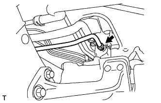
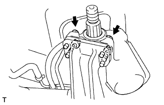
SEPARATE PRESSURE FEED TUBE ASSEMBLY
-
Using a union nut wrench, disconnect the pressure feed tube.
-
-
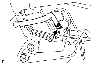
SEPARATE STEERING GEAR OUTLET RETURN TUBE
-
Remove the clip and disconnect the return hose.
-
Using a union nut wrench, disconnect the return tube.
-
-
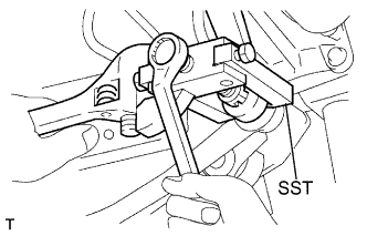
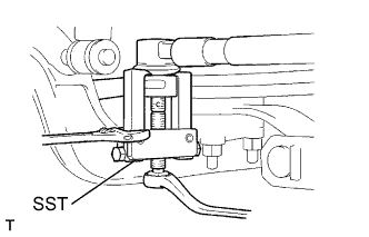
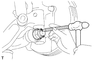
REMOVE STEERING DRAG LINK ASSEMBLY
-
Remove the 2 cotter pin and 2 nuts.
-
Using SST, disconnect the drag link from the pitman arm.
- SST
- 09628-62011
-
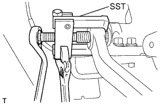
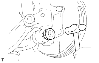
Using SST, disconnect the drag link from the knuckle arm.
- SST
- 09628-62011
-
-
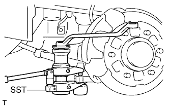
REMOVE PITMAN ARM
-
Remove the nut and spring washer.
-
Using SST, remove the pitman arm.
- SST
- 09628-62011
-
-
REMOVE POWER STEERING GEAR ASSEMBLY
-
Remove the 4 bolts, washers and power steering gear assembly.
-
-
REMOVE FRONT WHEEL
-
REMOVE STEERING TIE ROD
-
Remove the 2 cotter pin and 2 nuts.
-
Using SST, disconnect the 2 tie rod ends, and remove the steering tie rod.
- SST
- 09628-00011
-
-
REMOVE TIE ROD END SUB-ASSEMBLY LH
-
Loosen the lock nut.
-
Remove the tie rod end and lock nut.
-
-
REMOVE TIE ROD END SUB-ASSEMBLY RH
Tech Tips
Remove the RH side by the same procedures with the LH side.
-
REMOVE STEERING KNUCKLE ARM LH
-
Using a hammer and a chisel, unstake the lock nut.
-
Using a socket wrench (32 mm), remove the lock nut.
-
Using a hammer, remove the knuckle arm from the steering knuckle.
-
Remove the woodruff key from the knuckle arm.
-
-
REMOVE STEERING KNUCKLE ARM RH
Tech Tips
Remove the RH side by the same procedures with the LH side.
-
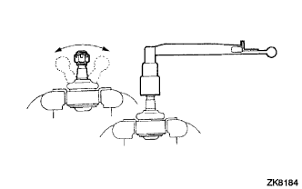
INSPECT STEERING DRAG LINK ASSEMBLY
-
Flip the ball joint stud back and forth 5 times as shown in the figure, before installing the nut.
-
Using a torque wrench, turn the nut continuously at a rate of 2 - 4 seconds per 1 turn and take the torque reading on the 5th turn.
Torque(Turning) 4 - 8 N*m (41 - 82 kgf*cm, 35 - 71 in.*lbf)
-
-
INSPECT TIE ROD END SUB-ASSEMBLY LH
-
Flip the ball joint stud back and forth 5 times as shown in the figure, before installing the nut.
-
Using a torque wrench, turn the nut continuously at a rate of 2 - 4 seconds per 1 turn and take the torque reading on the 5th turn.
Torque(Turning) 4 - 8 N*m (41 - 82 kgf*cm, 35 - 71 in.*lbf)
-