LOAD SENSING PROPORTIONING VALVE INSTALLATION

-
INSTALL LOAD SENSING SPRING BUSH AND BOOT KIT
-
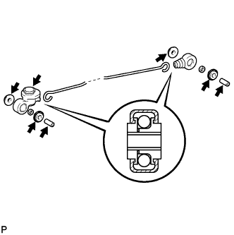
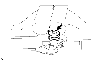
Apply lithium soap base glycol grease to the parts shown in the illustration.
Text in Illustration 
Lithium soap base glycol grease -
Install a new load sensing valve boot and a new load sensing spring boot to the load sensing spring.
-
Install 2 new No. 1 load sensing spring bushes, 2 new No. 2 load sensing spring bushes, 2 new plate washers and 2 collars to the load sensing valve boot and load sensing spring boot.
-
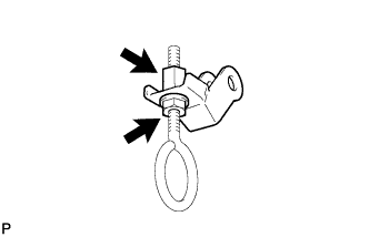
Temporarily install the nut, plate washer, No. 1 load sensing spring shackle and lock nut to the No. 2 load sensing spring shackle.
-
Install the 2 load sensing valve bushes and collar to the No. 2 load sensing spring shackle.
-
Temporarily install the 2 plate washers and No. 1 load sensing spring shackle with the nut, washer and bolt.
-
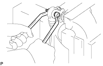
Tighten the nut while holding the bolt.
- Torque:
- 18 N*m { 184 kgf*cm, 13 ft.*lbf }
-
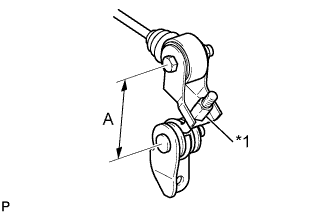
Text in Illustration *1 Lock Nut Turn the lock nut so that dimension A, shown in the illustration, is adjusted to approximately 78 mm (3.07 in.).
- Torque:
- 13 N*m { 127 kgf*cm, 9 ft.*lbf }
-
Install the No. 1 load sensing shackle bracket to the No. 2 load sensing spring shackle with the plate washer and nut.
- Torque:
- 13 N*m { 127 kgf*cm, 9 ft.*lbf }
-
-
INSTALL LOAD SENSING PROPORTIONING VALVE
-
Install the load sensing proportioning valve to the load sensing valve boot with the clip.
-
Temporarily install the load sensing proportioning valve and 2 plate washers to the load sensing valve bracket.
-
Temporarily install the load sensing valve set plate, 2 washers and 2 nuts.
-
Temporarily install the bolt, washer and nut.
-
Tighten the nut while holding the bolt.
- Torque:
- 18 N*m { 184 kgf*cm, 13 ft.*lbf }
-
Tighten the 2 nuts.
- Torque:
- 13 N*m { 127 kgf*cm, 9 ft.*lbf }
-
-
INSTALL LOAD SENSING WITH SPRING VALVE ASSEMBLY
-
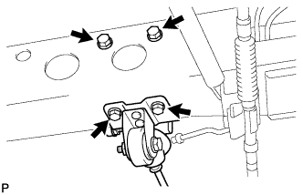
Install the load sensing with spring valve assembly with the 4 bolts.
- Torque:
- 25 N*m { 255 kgf*cm, 18 ft.*lbf }
-
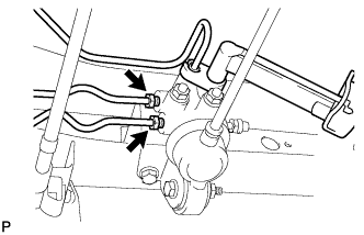
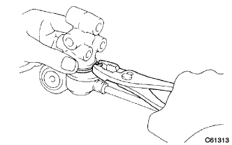
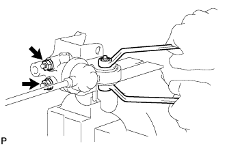
Using union nut wrench 10 mm, install the 3 brake tubes onto the load sensing proportioning valve.
- Torque:
- 15 N*m { 155 kgf*cm, 11 ft.*lbf }
Note
Use the formula to calculate special torque values for situations where a union nut wrench is combined with a torque wrench Click here.
-
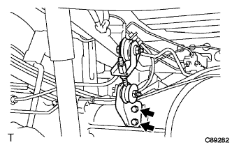
Install the No. 1 load sensing shackle bracket with the 2 bolts.
- Torque:
- 19 N*m { 194 kgf*cm, 14 ft.*lbf }
-
-
FILL RESERVOIR WITH BRAKE FLUID
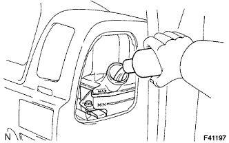
Fluid SAE J1703 or FMVSS No. 116 DOT3 -
BLEED MASTER CYLINDER
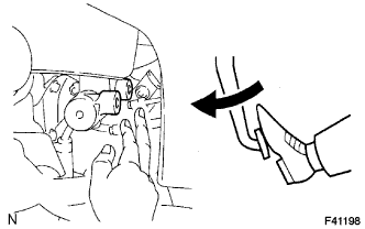
Tech Tips
If the master cylinder has been disassembled or if the reservoir becomes empty, bleed the air from the master cylinder.
-
Disconnect the brake lines from the master cylinder.
-
Slowly depress the brake pedal and hold it.
-
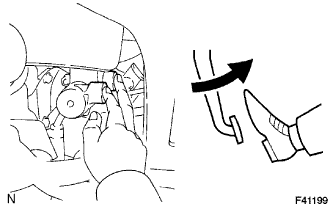
Block off the outer holes with your fingers, and release the brake pedal.
-
Repeat (b) and (c) 3 or 4 times.
-
-
BLEED BRAKE LINE
-
Connect the vinyl tube to the brake caliper.
-
Depress the brake pedal several times, then loosen the bleeder plug with the pedal held down.
-
At the point when fluid stops coming out, tighten the bleeder plug, then release the brake pedal.
-
Repeat (b) and (c) until all the air in the fluid has been bled out.
-
Repeat the above procedure to bleed the air out of the brake line for each wheel.
- Torque:
- 11 N*m { 110 kgf*cm, 8 ft.*lbf }
-
-
CHECK REAR WHEEL CYLINDER FLUID PRESSURE
-
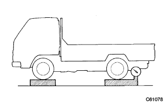
Set the rear axle load.
Standard Vehicle Model ABS Rear Axle Load
kN (kgf)
KDY221R-TBMDYW - 11.8 (1200) KDY221R-TBMDYW3 - 11.8 (1200) KDY221R-TLMGY - 8.3 (850) KDY221L-TBMDYW - 11.8 (1200) KDY221L-TBMDYW3 - 11.8 (1200) KDY231R-TBMGYW3 w/o ABS 14.7 (1500) w/ ABS 16.7 (1700) KDY231R-TLMKY - 8.3 (850) KDY231L-TBMGYW3 w/o ABS 14.7 (1500) w/ ABS 16.7 (1700) KDY231L-PBMEYW3 w/o ABS 14.7 (1500) w/ ABS 16.7 (1700) KDY231L-PSMBYW - 10.8 (1100) KDY231L-PSMBYW3 - 10.8 (1100) KDY251R-TBMGYW3 w/o ABS 14.7 (1500) w/ ABS 16.7 (1700) KDY251L-TBMGYW3 w/o ABS 14.7 (1500) w/ ABS 16.7 (1700) KDY251L-PBMEYW3 w/o ABS 14.7 (1500) w/ ABS 16.7 (1700) KDY261L-TBMGYW3 w/o ABS 14.7 (1500) w/ ABS 16.7 (1700) KDY261L-PBMEYW3 w/o ABS 14.7 (1500) w/ ABS 16.7 (1700) LY230R-TBMGSN3 - 13.7 (1400) LY225R-TBMDS - 7.8 (800) LY225R-TBMDS3 - 7.8 (800) LY225L-TBMDS - 7.8 (800) LY225L-TBMDS3 - 7.8 (800) LY235R-TBMFS - 8.3 (850) LY235R-TBMFS3 - 8.3 (850) LY235L-TBMFS - 8.3 (850) LY235L-TBMFS3 - 8.3 (850) -
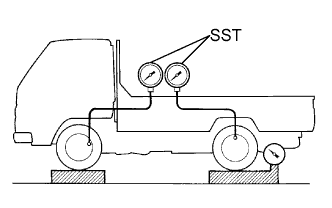
Install the SST to the front and rear wheel cylinders.
- SST
- 09709-29018
-
Bleed the air from the brake system.
-
Measure the rear wheel cylinder fluid pressure.
-
Raise the front wheel cylinder fluid pressure to 6.9 MPa (70.4 kgf/cm2) by pressing the brake pedal, and measure the rear wheel cylinder fluid pressure.
Standard Vehicle Model Rear Wheel Cylinder Fluid Pressure
MPa (kgf/cm2)
KDY221R-TBMDYW 3.9 +/- 0.59 (39.8 +/- 6.0) KDY221R-TBMDYW3 3.9 +/- 0.59 (39.8 +/- 6.0) KDY221R-TLMGY 4.3 +/- 0.59 (43.8 +/- 6.0) KDY221L-TBMDYW 3.9 +/- 0.59 (39.8 +/- 6.0) KDY221L-TBMDYW3 3.9 +/- 0.59 (39.8 +/- 6.0) KDY231R-TBMGYW3 5.8 +/- 0.59 (59.1 +/- 6.0) KDY231R-TLMKY 4.3 +/- 0.59 (43.8 +/- 6.0) KDY231L-TBMGYW3 5.8 +/- 0.59 (59.1 +/- 6.0) KDY231L-PBMEYW3 5.8 +/- 0.59 (59.1 +/- 6.0) KDY231L-PSMBYW 3.9 +/- 0.59 (39.8 +/- 6.0) KDY231L-PSMBYW3 3.9 +/- 0.59 (39.8 +/- 6.0) KDY251R-TBMGYW3 5.8 +/- 0.59 (59.1 +/- 6.0) KDY251L-TBMGYW3 5.8 +/- 0.59 (59.1 +/- 6.0) KDY251L-PBMEYW3 5.8 +/- 0.59 (59.1 +/- 6.0) KDY261L-TBMGYW3 5.8 +/- 0.59 (59.1 +/- 6.0) KDY261L-PBMEYW3 5.8 +/- 0.59 (59.1 +/- 6.0) LY230R-TBMGSN3 5.8 +/- 0.59 (59.1 +/- 6.0) LY225R-TBMDS 3.9 +/- 0.59 (39.8 +/- 6.0) LY225R-TBMDS3 3.9 +/- 0.59 (39.8 +/- 6.0) LY225L-TBMDS 3.9 +/- 0.59 (39.8 +/- 6.0) LY225L-TBMDS3 3.9 +/- 0.59 (39.8 +/- 6.0) LY235R-TBMFS 3.9 +/- 0.59 (39.8 +/- 6.0) LY235R-TBMFS3 3.9 +/- 0.59 (39.8 +/- 6.0) LY235L-TBMFS 3.9 +/- 0.59 (39.8 +/- 6.0) LY235L-TBMFS3 3.9 +/- 0.59 (39.8 +/- 6.0) -
Raise the front wheel cylinder fluid pressure to 11.8 MPa (120.3 kgf/cm2) by pressing the brake pedal, and measure the rear wheel cylinder fluid pressure.
Standard Vehicle Model Rear Wheel Cylinder Fluid Pressure
MPa (kgf/cm2)
KDY221R-TBMDYW 4.9 +/- 0.69 (50.0 +/- 7.0) KDY221R-TBMDYW3 4.9 +/- 0.69 (50.0 +/- 7.0) KDY221R-TLMGY 5.3 +/- 0.69 (54.0 +/- 7.0) KDY221L-TBMDYW 4.9 +/- 0.69 (50.0 +/- 7.0) KDY221L-TBMDYW3 4.9 +/- 0.69 (50.0 +/- 7.0) KDY231R-TBMGYW3 7.6 +/- 0.69 (77.5 +/- 7.0) KDY231R-TLMKY 5.3 +/- 0.69 (54.0 +/- 7.0) KDY231L-TBMGYW3 7.6 +/- 0.69 (77.5 +/- 7.0) KDY231L-PBMEYW3 7.6 +/- 0.69 (77.5 +/- 7.0) KDY231L-PSMBYW 4.9 +/- 0.69 (50.0 +/- 7.0) KDY231L-PSMBYW3 4.9 +/- 0.69 (50.0 +/- 7.0) KDY251R-TBMGYW3 7.6 +/- 0.69 (77.5 +/- 7.0) KDY251L-TBMGYW3 7.6 +/- 0.69 (77.5 +/- 7.0) KDY251L-PBMEYW3 7.6 +/- 0.69 (77.5 +/- 7.0) KDY261L-TBMGYW3 7.6 +/- 0.69 (77.5 +/- 7.0) KDY261L-PBMEYW3 7.6 +/- 0.69 (77.5 +/- 7.0) LY230R-TBMGSN3 7.6 +/- 0.69 (77.5 +/- 7.0) LY225R-TBMDS 4.9 +/- 0.69 (50.0 +/- 7.0) LY225R-TBMDS3 4.9 +/- 0.69 (50.0 +/- 7.0) LY225L-TBMDS 4.9 +/- 0.69 (50.0 +/- 7.0) LY225L-TBMDS3 4.9 +/- 0.69 (50.0 +/- 7.0) LY235R-TBMFS 4.9 +/- 0.69 (50.0 +/- 7.0) LY235R-TBMFS3 4.9 +/- 0.69 (50.0 +/- 7.0) LY235L-TBMFS 4.9 +/- 0.69 (50.0 +/- 7.0) LY235L-TBMFS3 4.9 +/- 0.69 (50.0 +/- 7.0) Note
-
The pedal should not be depressed twice or released while the front wheel cylinder fluid pressure is being set.
-
Read the value of the rear wheel cylinder fluid pressure after adjusting and holding the front wheel cylinder fluid pressure for 2 seconds.
If the result is not as specified, adjust the load sensing proportioning valve.
-
-
-
Calculate the rear wheel cylinder fluid pressure in accordance with the procedure below when the rear axle load can not be adjusted to the specified axle weight.
-
Measure the rear axle load.
-
Calculate the fluid pressure crossover point at the measured rear axle load by applying the following formula.
Fluid pressure crossover point P = (Cp - Bp) / (Cw - Bw) x (W - Bw) + Bp P (MPa) Fluid pressure crossover point at "W" W (kN) Measured rear axle load Cp (MPa) Fluid pressure crossover point at "C" Bp (MPa) Fluid pressure crossover point at "B" Cw (kN) Rear axle load at "C" Bw (kN) Rear axle load at "B" 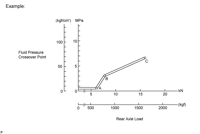
ABC point data table Vehicle Model ABS A B C kN (kgf) MPa
(kgf/cm2)
kN (kgf) MPa
(kgf/cm2)
kN (kgf) MPa
(kgf/cm2)
KDY221R-TBMDYW - 7.2 (730) 0.5 (5.1) 7.7 (789) 1.4 (14.5) 15.3 (1565) 4.6 (47.3) KDY221R-TBMDYW3 - 7.2 (730) 0.5 (5.1) 7.7 (789) 1.4 (14.5) 15.3 (1565) 4.6 (47.3) KDY221R-TLMGY - 6.0 (608) 0.5 (5.1) 6.6 (675) 2.3 (23.4) 19.4 (1980) 10.5 (107.1) KDY221L-TBMDYW - 7.2 (730) 0.5 (5.1) 7.7 (789) 1.4 (14.5) 15.3 (1565) 4.6 (47.3) KDY221L-TBMDYW3 - 7.2 (730) 0.5 (5.1) 7.7 (789) 1.4 (14.5) 15.3 (1565) 4.6 (47.3) KDY231R-TBMGYW3 w/o ABS 10.8 (1100) 0.5 (5.1) 12.0 (1224) 3.1 (32.1) 19.2 (1960) 8.4 (85.6) w/ ABS 11.4 (1167) 0.5 (5.1) 12.0 (1224) 1.7 (17.5) 19.2 (1960) 7.0 (71.1) KDY231R-TLMKY - 6.0 (608) 0.5 (5.1) 6.6 (675) 2.3 (23.4) 19.9 (2030) 10.7 (109.3) KDY231L-TBMGYW3 w/o ABS 10.8 (1100) 0.5 (5.1) 12.0 (1224) 3.1 (32.1) 19.2 (1960) 8.4 (85.6) w/ ABS 11.4 (1167) 0.5 (5.1) 12.0 (1224) 1.7 (17.5) 19.2 (1960) 7.0 (71.1) KDY231L-PBMEYW3 w/o ABS 10.8 (1100) 0.5 (5.1) 12.0 (1224) 3.1 (32.1) 20.7 (2110) 9.5 (96.5) w/ ABS 11.4 (1167) 0.5 (5.1) 12.0 (1224) 1.7 (17.5) 20.7 (2110) 8.0 (82.0) KDY231L-PSMBYW - 6.9 (704) 0.5 (5.1) 7.7 (789) 1.8 (18.7) 15.9 (1620) 5.3 (53.8) KDY231L-PSMBYW3 - 6.9 (704) 0.5 (5.1) 7.7 (789) 1.8 (18.7) 15.9 (1620) 5.3 (53.8) KDY251R-TBMGYW3 w/o ABS 10.8 (1100) 0.5 (5.1) 12.0 (1224) 3.1 (32.1) 18.6 (1900) 8.0 (81.2) w/ ABS 11.4 (1167) 0.5 (5.1) 12.0 (1224) 1.7 (17.5) 18.6 (1900) 6.5 (66.7) KDY251L-TBMGYW3 w/o ABS 10.8 (1100) 0.5 (5.1) 12.0 (1224) 3.1 (32.1) 18.6 (1900) 8.0 (81.2) w/ ABS 11.4 (1167) 0.5 (5.1) 12.0 (1224) 1.7 (17.5) 18.6 (1900) 6.5 (66.7) KDY251L-PBMEYW3 w/o ABS 10.8 (1100) 0.5 (5.1) 12.0 (1224) 3.1 (32.1) 18.1 (1845) 7.6 (77.2) w/ ABS 11.4 (1167) 0.5 (5.1) 12.0 (1224) 1.7 (17.5) 18.1 (1845) 6.1 (62.7) KDY261L-TBMGYW3 w/o ABS 10.8 (1100) 0.5 (5.1) 12.0 (1224) 3.1 (32.1) 18.6 (1900) 7.9 (80.9) w/ ABS 11.4 (1167) 0.5 (5.1) 12.0 (1224) 1.7 (17.5) 18.6 (1900) 6.5 (66.3) KDY261L-PBMEYW3 w/o ABS 10.8 (1100) 0.5 (5.1) 12.0 (1224) 3.1 (32.1) 18.1 (1845) 7.6 (77.2) w/ ABS 11.4 (1167) 0.5 (5.1) 12.0 (1224) 1.7 (17.5) 18.1 (1845) 6.1 (62.7) LY230R-TBMGSN3 - 10.5 (1067) 0.5 (5.1) 12.0 (1224) 3.9 (39.4) 19.6 (2000) 9.4 (95.8) LY225R-TBMDS - 6.1 (625) 0.5 (5.1) 7.8 (797) 3.1 (31.7) 15.8 (1610) 6.5 (66.1) LY225R-TBMDS3 - 6.1 (625) 0.5 (5.1) 7.8 (797) 3.1 (31.7) 15.8 (1610) 6.5 (66.1) LY225L-TBMDS - 6.1 (625) 0.5 (5.1) 7.8 (797) 3.1 (31.7) 15.8 (1610) 6.5 (66.1) LY225L-TBMDS3 - 6.1 (625) 0.5 (5.1) 7.8 (797) 3.1 (31.7) 15.8 (1610) 6.5 (66.1) LY235R-TBMFS - 5.7 (584) 0.5 (5.1) 7.3 (745) 2.7 (27.5) 19.5 (1990) 7.7 (78.7) LY235R-TBMFS3 - 5.7 (584) 0.5 (5.1) 7.3 (745) 2.7 (27.5) 19.5 (1990) 7.7 (78.7) LY235L-TBMFS - 5.7 (584) 0.5 (5.1) 7.3 (745) 2.7 (27.5) 19.5 (1990) 7.7 (78.7) LY235L-TBMFS3 - 5.7 (584) 0.5 (5.1) 7.3 (745) 2.7 (27.5) 19.5 (1990) 7.7 (78.7) -
Calculate the rear wheel cylinder fluid pressure when front wheel cylinder fluid pressure is 6.9 MPa (70.4 kgf/cm2) in the following formula.
Rear wheel cylinder fluid pressure formula Vehicle Model Rear wheel cylinder fluid pressure formula KDY221R-TBMDYW P + (6.9 - P) x 0.2 KDY221R-TBMDYW3 P + (6.9 - P) x 0.2 KDY221R-TLMGY P + (6.9 - P) x 0.2 KDY221L-TBMDYW P + (6.9 - P) x 0.2 KDY221L-TBMDYW3 P + (6.9 - P) x 0.2 KDY231R-TBMGYW3 P + (6.9 - P) x 0.37 KDY231R-TLMKY P + (6.9 - P) x 0.2 KDY231L-TBMGYW3 P + (6.9 - P) x 0.37 KDY231L-PBMEYW3 P + (6.9 - P) x 0.37 KDY231L-PSMBYW P + (6.9 - P) x 0.2 KDY231L-PSMBYW3 P + (6.9 - P) x 0.2 KDY251R-TBMGYW3 P + (6.9 - P) x 0.37 KDY251L-TBMGYW3 P + (6.9 - P) x 0.37 KDY251L-PBMEYW3 P + (6.9 - P) x 0.37 KDY261L-TBMGYW3 P + (6.9 - P) x 0.37 KDY261L-PBMEYW3 P + (6.9 - P) x 0.37 LY230R-TBMGSN3 P + (6.9 - P) x 0.37 LY225R-TBMDS P + (6.9 - P) x 0.2 LY225R-TBMDS3 P + (6.9 - P) x 0.2 LY225L-TBMDS P + (6.9 - P) x 0.2 LY225L-TBMDS3 P + (6.9 - P) x 0.2 LY235R-TBMFS P + (6.9 - P) x 0.2 LY235R-TBMFS3 P + (6.9 - P) x 0.2 LY235L-TBMFS P + (6.9 - P) x 0.2 LY235L-TBMFS3 P + (6.9 - P) x 0.2 Service limit +/- 0.59 MPa (+/- 6.0 kgf/cm2) If the result is not as specified, adjust the load sensing proportioning valve.
-
Example:
Vehicle Model LY225R-TBMDS Measured Rear Axle Load 9.8 kN (1000 kgf) Front Wheel Cylinder Fluid Pressure 6.9 MPa (70.4 kgf/cm2)
Standard (ABC point data table) A B C kN (kgf) MPa (kgf/cm2)
kN (kgf) MPa (kgf/cm2)
kN (kgf) MPa (kgf/cm2)
6.1 (625) 0.5 (5.1) 7.8 (797) 3.1 (31.7) 15.8 (1610) 6.5 (66.1) 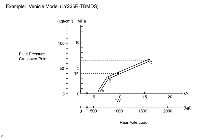
Fluid pressure crossover point P = (Cp - Bp) / (Cw - Bw) x (W - Bw) + Bp P (MPa) Fluid pressure crossover point at "W" W (kN) Measured rear axle load Cp (MPa) Fluid pressure crossover point at "C" Bp (MPa) Fluid pressure crossover point at "B" Cw (kN) Rear axle load at "C" Bw (kN) Rear axle load at "B" Rear wheel cylinder fluid pressure P + (6.9 - P) x 0.2 P = (6.5 - 3.1) / (15.8 - 7.8) x (9.8 - 7.8) + 3.1
P = 3.95 MPa
Rear wheel cylinder fluid pressure = 3.95 + (6.9 - 3.95) x 0.2
Rear wheel cylinder fluid pressure = 4.5 MPa (45.9 kgf/cm2)
-
-
-
CHECK FLUID LEVEL IN RESERVOIR
-
Check the fluid level and add fluid if necessary.
Fluid SAE J1703 or FMVSS No. 116 DOT3
-
-
INSPECT FOR BRAKE FLUID LEAK