LOAD SENSING PROPORTIONING VALVE REMOVAL

-
DRAIN BRAKE FLUID
Note
Immediately wash off any brake fluid that comes into contact with any painted surfaces.
-
REMOVE LOAD SENSING WITH SPRING VALVE ASSEMBLY
-
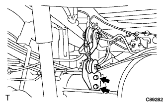
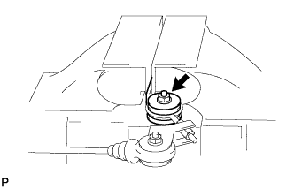
Remove the 2 bolts and separate the No. 1 load sensing shackle bracket.
-
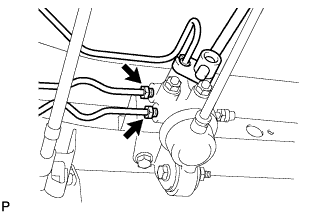
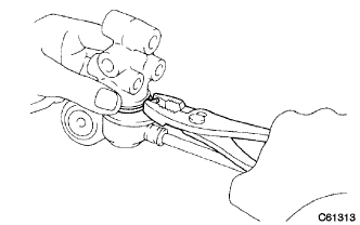
Using union nut wrench 10 mm, separate the 3 brake tubes from the load sensing proportioning valve.
-
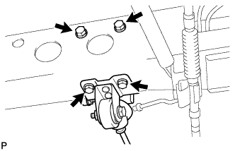
Remove the 4 bolts and separate the load sensing valve bracket.
-
-
REMOVE LOAD SENSING PROPORTIONING VALVE
-
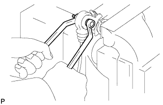
Fix the load sensing valve bracket in a vise between aluminum plates.
Note
Do not overtighten the vise.
-
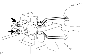
Remove the nut and washer while holding the bolt.
-
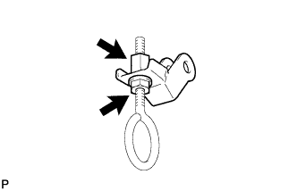
Remove the 2 nuts, 2 washers and load sensing valve set plate.
-
Remove the load sensing proportioning valve and 2 plate washers from the load sensing valve bracket.
-
Remove the clip and load sensing proportioning valve.
-
-
REMOVE LOAD SENSING SPRING BUSH AND BOOT KIT
-
Fix the No. 1 load sensing shackle bracket in a vise between aluminum plates.
Note
Do not overtighten the vise.
-
Remove the nut, plate washer and No. 1 load sensing shackle bracket from the No. 2 load sensing spring shackle.
-
Remove the nut and washer while holding the bolt.
-
Remove the No. 1 load sensing spring shackle and 2 plate washers.
-
Remove the collar and 2 load sensing valve bushes from the No. 2 load sensing spring shackle.
-
Remove the lock nut, No. 1 load sensing spring shackle, plate washer and nut from the No. 2 load sensing spring shackle.
-
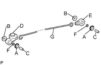
Remove the following parts from the load sensing spring.
Symbol Name Quantity A No. 1 load sensing spring bush 2 B No. 2 load sensing spring bush 2 C Collar 2 D Load sensing valve boot 1 E Load sensing spring boot 1 F Plate washer 2 G Load sensing spring 1
-
-
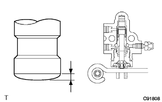
INSPECT LOAD SENSING PROPORTIONING VALVE
-
Inspect contact surface wear between the control valve piston and spring.
Standard 0.7 mm (0.028 in.) Note
Do not disassemble the load sensing proportioning valve.
-