STEERING GEAR REASSEMBLY

-
INSTALL POWER PISTON OIL SEAL
-
Coat a new oil seal with power steering fluid and install it.
-
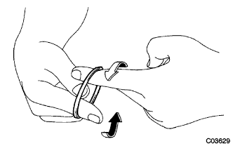
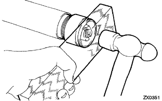
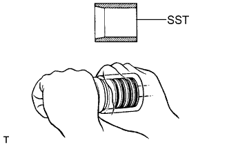
Expand a new teflon ring with your fingers.
Note
Be careful no to overexpand the ring.
-
Coat the ring with power steering fluid.
-
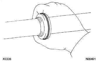
Install the ring to the rack, and settle it down with your fingers.
Note
Be careful not to damage the oil seal.
-
-
INSTALL POWER STEERING CYLINDER TUBE OIL SEAL

-
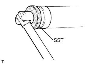
Coat the spacer with power steering fluid.
-
Coat a new oil seal lip with power steering fluid.
-
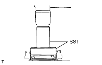
Using SST, press in the spacer and oil seal.
- SST
- 09950-60010 ( 09951-00300, 09951-00470, 09952-06010 )
- 09950-70010 ( 09951-07360 )
Note
-
Make sure to install the oil seal facing in the correct direction.
-
Take care that the oil seal does not get reversed as you install it.
Tech Tips
Install the cylinder end stopper temporarily to make it be a guide for SST.
-
-
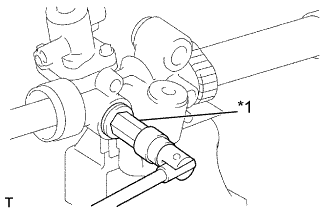
INSTALL POWER STEERING RACK
-
Coat SST with power steering fluid.
- SST
- 09631-00350
-
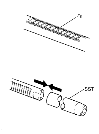
Install SST to the rack.
Text in Illustration *a Rack Teeth End Tech Tips
Is necessary, scrape the burrs off the rack teeth end and burnish.
-
Install the rack into the rack housing.
-
Remove the SST.
-
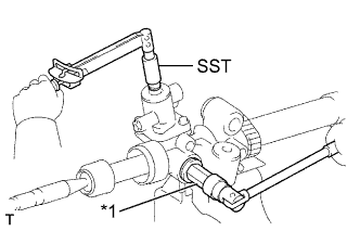
Coat SST with power steering fluid.
- SST
- 09631-00350
-
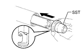
Install SST to the steering rack opposite end.
-
Coat a new oil seal lip with power steering fluid, and install the oil seal by pushing it without tilting.
Note
-
Make sure to install the oil seal facing in the correct direction.
-
Be careful not to damage the oil seal lip.
-
-
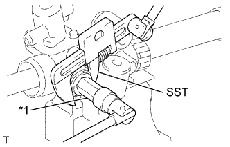
Remove the SST.
-
-
INSTALL CYLINDER END STOPPER
-
Coat a new O-ring with power steering fluid, and install it to the stopper.
-
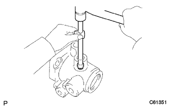
Using a wooden block and a hammer, drive in the stopper until it is tightly installed.
Note
Be careful no to damage the O-ring.
-
Using SST, torque the stopper.
- SST
- 09631-36010
- Torque:
- 78 N*m { 795 kgf*cm, 57 ft.*lbf }
-
-
AIR TIGHTNESS TEST

-
Install SST to the unions of the rack housing.
- SST
- 09631-12071 ( 09633-00010 )
-
Apply 53.33 kPa (400 mmHg, 15.75 in.Hg) of vacuum for about 30 seconds.
-
Check that there is no change in the vacuum.
If there is change in the vacuum, check the installation of the oil seals.
-
-
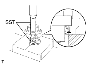
INSTALL POWER STEERING CONTROL VALVE UPPER OIL SEAL
-
Coat a new oil seal lip with power steering fluid.
-
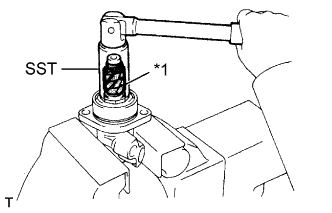
Using SST, press in the oil seal.
- SST
- 09950-60010 ( 09951-00180, 09951-00320, 09951-00340, 09952-06010 )
- 09950-70010 ( 09951-07150 )
Note
Make sure to install the oil seal facing in the correct direction.
-
Coat a new bearing with molybdenum disulfide lithium base grease.
-
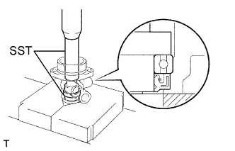
Using SST, press in the baring.
- SST
- 09950-60010 ( 09951-00180, 09951-00320, 09951-00340, 09952-06010 )
- 09950-70010 ( 09951-07150 )
-
-
INSTALL POWER STEERING CONTROL VALVE
-
Using a plastic hammer and a sliding handle, lightly tap in a new union seat.
Note
Before installing the union seat, remove dust sticking to the control valve housing.
-
Coat the rings with power steering fluid.
-
Expand 4 new rings with your fingers.
Note
Be careful not to overexpand the ring.
-
Install the rings to the control valve assembly, and settle them down with your fingers.
-
Carefully slide the tapered end of SST over the rings until the ring fits to the steering rack.
- SST
- 09631-20081
Note
Be careful not to overexpand the ring.
-
Coat the teflon rings with power steering fluid.
-

Text in Illustration *1 Vinyl Tape To prevent oil seal lip damage, wind vinyl tape on the serrated port of the control valve shaft.
-
Push the valve assembly into the control valve housing.
Note
Be careful not to damage the teflon rings and oil seal lip.
-
Coat a new O-ring with power steering fluid, and install it to the bearing guide nut.
-
Coat a new oil seal lip with power steering fluid.
-
Using SST and a hammer, drive in the oil seal.
- SST
- 09950-60010 ( 09951-00390 )
- 09950-70010 ( 09951-07100 )
Note
Make sure to install the oil seal facing in the correct direction.
-
Lightly mount the control valve assembly between aluminum plates in a vise.
-
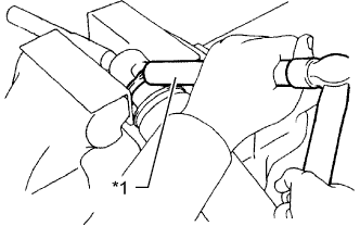
To prevent oil seal lip damage, wind vinyl tape on the pinion part of the control valve shaft.
-
Text in Illustration *1 Vinyl Tape Using SST, torque the guide nut.
- SST
- 09631-20060
- Torque:
- 24.5 N*m { 250 kgf*cm, 18 ft.*lbf }
Note
Be careful not to damage the oil seal lip.
-

Using a punch and a hammer, stake the nut.
-
Coat a new O-ring with power steering fluid, and install it to the valve housing.
-

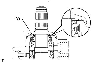
Text in Illustration *a Grease filling Apply molybdenum disulfide base grease for the needle roller baring inside the rack housing in the illustrated portion.
Volume of grease applied Approximately 2 g (0.07 oz) -
Install the control valve assembly with the 2 bolts.
- Torque:
- 18.1 N*m { 184 kgf*cm, 13 ft.*lbf }
-
-
INSTALL RACK GUIDE
Text in Illustration *1 Hexagon Wrench
-
Install the rack guide and spring.
-
Apply sealant to 2 or 3 threads of the rack guide spring cap.
Sealant Toyota Genuine Adhesive 1344, THREE BOND 1344, LOCTITE 242 or equivalent -
Using a hexagon wrench (24 mm), temporarily install the spring cap.
-
-
ADJUST TOTAL PRELOAD
-
To prevent the steering rack teeth from damaging the oil seal lip, temporarily install the RH and LH rack ends.
-
Text in Illustration *1 Hexagon Wrench Using a hexagon wrench (24 mm), tighten the rack guide spring cap.
- Torque:
- 24.5 N*m { 250 kgf*cm, 18 ft.*lbf }
-
Return the cap 30°.
-

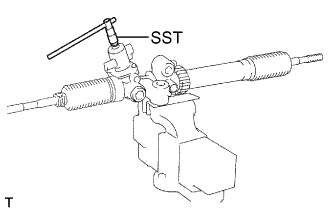
Using SST, turn the control valve shaft right and left 1 or 2 times.
- SST
- 09616-00011
-
Using a hexagon wrench (24 mm), loosen the cap until the rack guide spring is not functioning.
-
Text in Illustration *1 Hexagon Wrench Using SST, a torque wrench and a hexagon wrench (24 mm), tighten the cap until the preload is within specification.
- SST
- 09616-00011
Preload (turning) 0.8 - 1.2 N*m (8.1 - 12.2 kgf*cm, 7.1 - 10.6 in.*lbf) Note
Adjustment should be done in the tightening direction of the spring cap.
-
Apply sealant to 2 or 3 threads of the lock nut.
Sealant Toyota Genuine Adhesive 1344, THREE BOND 1344, LOCTITE 242 or equivalent -
Temporarily install the lock nut.
-
Text in Illustration *1 Hexagon Wrench Using a hexagon wrench (24 mm), holding the rack guide spring cap rotating, and using SST, torque the nut.
- SST
- 09922-10010
- Torque:
- 49 N*m { 500 kgf*cm, 36 ft.*lbf, for use with SST }
Note
Use SST 09922-10010 in the direction shown in the illustration.
Tech Tips
Use a torque wrench with a fulcrum length of 345 mm (13.58 in.).
-
Recheck the total preload.
Preload (turning) 0.8 - 1.2 N*m (8.1 - 12.2 kgf*cm, 7.1 - 10.6 in.*lbf) -
Remove the RH and LH rack ends.
-
-
INSPECT POWER STEERING RACK
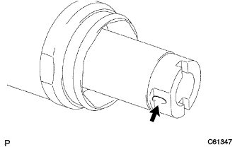
-
Insert a wire into the vent hole of the steering rack by 30 mm(1.18 in.), and ensure that the vent hole is not clogged with grease.
Tech Tips
If the hole is clogged, the pressure inside the boot will change after it is assembled and the steering wheel is turned.
-
-
INSTALL STEERING RACK END SUB-ASSEMBLY
-
Install a new claw washer, and temporarily tighten the rack end.
Tech Tips
Align the claws of the washer with the steering rack grooves.
-
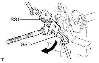
Using SST to hold the steering rack steady, and using SST, torque the rack end RH.
- SST
- 09922-10010
- Torque:
- 74.3 N*m { 758 kgf*cm, 55 ft.*lbf, for use with SST }
Note
Use SST 09922-10010 in the direction shown in the illustration.
Tech Tips
Use a torque wrench with a fulcrum length of 380 mm (14.9 in.).
-

Using SST to hold the steering rack steady, and using SST, torque the rack end LH.
- Torque:
- 74.3 N*m { 758 kgf*cm, 55 ft.*lbf, for use with SST }
Note
Use SST 09922-10010 in the direction shown in the illustration.
Tech Tips
Use a torque wrench with a fulcrum length of 380 mm (14.9 in.).
-
Text in Illustration *1 Brass Bar Using a brass bar and a hammer, stake the washer.
Note
Avoid any impact to the rack.
-
Employ the same manner described above to the other side.
-
-
INSTALL STEERING RACK BOOT NO.1
-
Install the boot.
Note
Be careful not to damage or twist the boot.
-
-
INSTALL STEERING RACK BOOT NO.2
Note
Install the No.2 side by the same procedures with the No.1 side.
-
INSTALL STEERING RACK BOOT NO.1 CLAMP
-
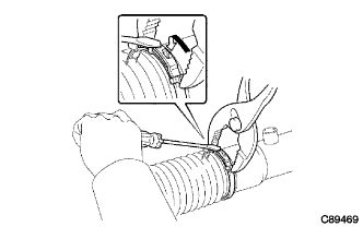
Using pliers and a screwdriver, install the clamp.
-
Install the clip.
-
Employ the same manner described above to the other side.
-
-
INSTALL STEERING RACK BOOT NO.2 CLAMP
Tech Tips
Install the No.2 side by the same procedures with the No.1 side.
-
INSPECT RACK & PINION POWER STEERING GEAR ASSEMBLY
-
Using SST, check that the rack boot stretches smoothly when the control valve shaft is being rotated.
- SST
- 09616-00011
-
Text in Illustration *a Grease filling Apply MP grease in the illustrated portion.
-
Install the dust cover.
-
Using a union nut wrench, install the 2 turn pressure tubes.
- Torque:
- 22 N*m { 223 kgf*cm, 16 ft.*lbf, for use with union nut wrench }
Tech Tips
-
Use a torque wrench with a fulcrum length of 300 mm (11.81 in.).
-
This torque value is effective in case that a union nut wrench is parallel to a torque wrench.
-
-
INSTALL TIE ROD END SUB-ASSEMBLY LH
-
Screw the lock nut and tie rod end onto the rack end until the matchmarks are aligned.
-
After adjusting toe-in, torque the nut.
-
Employ the same side manner described above to the other side.
-
-
INSTALL TIE ROD END SUB-ASSEMBLY RH
Tech Tips
Install the RH side by the same procedures with the LH side.