STEERING GEAR INSTALLATION

-
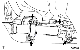
INSTALL RACK & PINION POWER STEERING GEAR ASSEMBLY
-
Install the PS gear assembly with the bolt washer and nut.
- Torque:
- 120 N*m { 1224 kgf*cm, 87 ft.*lbf }
-
Install the grommet and bracket with the 2 bolts.
- Torque:
- 120 N*m { 1224 kgf*cm, 87 ft.*lbf }
-
-
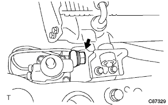
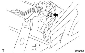
CONNECT PRESSURE FEED TUBE ASSEMBLY
-
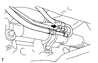
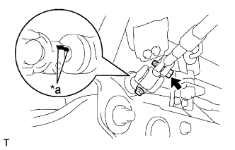
Connect the tube with the union bolt and a new gasket.
- Torque:
- 42.1 N*m { 430 kgf*cm, 31 ft.*lbf }
-
-
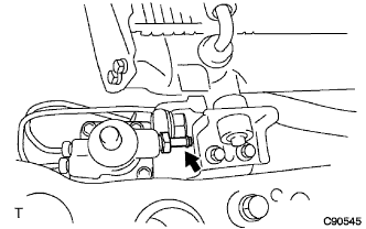
CONNECT STEERING GEAR OUTLET RETURN TUBE
-
Install the return tube.
- Torque:
- 44 N*m { 450 kgf*cm, 33 ft.*lbf }
-
Face the claw to the vehicle is front, and install the return hose to the PS gear assembly with the clip.
-
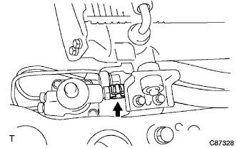
Install the hose with bolt (LHD steering position type only).
- Torque:
- 18 N*m { 184 kgf*cm, 13 ft.*lbf }
-
-
INSTALL STEERING BEVEL GEAR ASSEMBLY
-
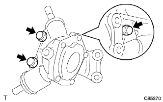
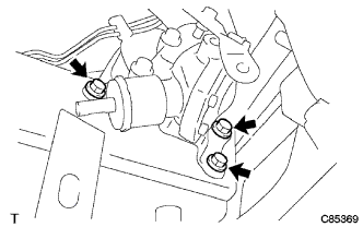
Install the housing bracket with the 3 bolts.
- Torque:
- 39 N*m { 400 kgf*cm, 29 ft.*lbf }
-
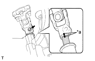
Text in Illustration *a Matchmark Install the steering shaft with the bolt hole matched to the notch of the bevel gear.
-
Install the 3 bolts of the bevel gear.
- Torque:
- 52 N*m { 530 kgf*cm, 38 ft.*lbf }
-
Install the bracket of the transmission control cable with the bolt (LHD steering position type only).
- Torque:
- 37 N*m { 377 kgf*cm, 27 ft.*lbf }
-
Install the bracket of parking brake cable with the bolt (RHD steering position type only).
- Torque:
- 37 N*m { 377 kgf*cm, 27 ft.*lbf }
-
Text in Illustration *a Matchmark Tighten the bolt.
- Torque:
- 35 N*m { 357 kgf*cm, 26 ft.*lbf }
-
-
TEMPORARILY TIGHTEN STEERING SLIDING YOKE SUB-ASSEMBLY
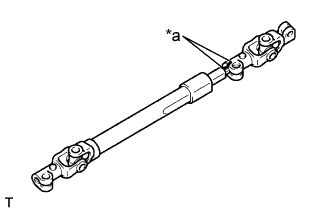
Text in Illustration *a Matchmark
-
Install the shaft cover.
-
Align the matchmarks on the sliding yoke and the torque shaft.
-
Temporary tighten the bolt.
-
-
INSTALL STEERING TORQUE SHAFT ASSEMBLY
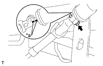
Text in Illustration *a Matchmark
-
Align the matchmarks on the torque shaft and bevel gear.
-
Tighten the bolt.
- Torque:
- 35 N*m { 357 kgf*cm, 26 ft.*lbf }
-
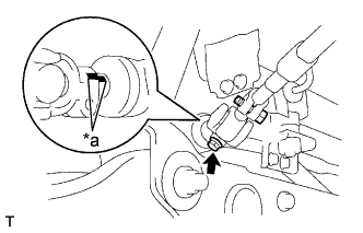
Text in Illustration *a Matchmark Align the matchmarks on the sliding yoke and steering gear.
-
Tighten the bolt.
- Torque:
- 35 N*m { 357 kgf*cm, 26 ft.*lbf }
-
-
FULLY TIGHTEN STEERING SLIDING YOKE SUB-ASSEMBLY
Text in Illustration *a Matchmark
-
Fully tighten the bolt.
- Torque:
- 35 N*m { 357 kgf*cm, 26 ft.*lbf }
-
Install the steering link protector UPR and steering link protector LWR with the 3 bolts.
-
-
CONNECT TIE ROD END SUB-ASSEMBLY LH
-
Connect the tie rod end to the knuckle arm.
-
Install the nuts and new cotter pin.
- Torque:
- 91 N*m { 928 kgf*cm, 67 ft.*lbf }
-
-
CONNECT TIE ROD END SUB-ASSEMBLY RH
Tech Tips
Connect the RH side by the same procedures with the LH side.
-
INSTALL FRONT WHEEL
- Torque:
- Full just low
- 135 N*m { 1377 kgf*cm, 100 ft.*lbf }
- Except full just low
- 365 N*m { 3722 kgf*cm, 269 ft.*lbf }
-
PLACE FRONT WHEELS FACING STRAIGHT AHEAD
-
INSTALL TURN SIGNAL SWITCH ASSEMBLY (W/ SRS AIRBAG)
-
INSTALL SPIRAL CABLE SUB-ASSEMBLY (W/ SRS AIRBAG)
-
INSTALL STEERING COLUMN COVER LWR (W/ SRS AIRBAG)
-
CENTER SPIRAL CABLE (W/ SRS AIRBAG)
-
Check that the ignition switch is OFF.
-
Check that the battery negative terminal is disconnected.
Note
Do not start the operation for 90 seconds after removing the terminal.
-
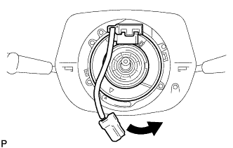
Turn the cable counterclockwise by hand until it becomes harder to turn.
Tech Tips
The cable will rotate about 3.5 turns to either left or right of the center.
-
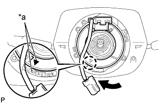
Text in Illustration *a Matchmarks Then rotate the cable clockwise about 3.5 turns to align the marks.
-
-
INSTALL STEERING WHEEL ASSEMBLY (W/ SRS AIRBAG)
-
Align the matchmarks on the steering wheel assembly with the one on the steering main shaft.
-
Install the steering wheel set nut.
- Torque:
- 50 N*m { 510 kgf*cm, 37 ft.*lbf }
-
-
INSPECT STEERING WHEEL CENTER POINT (W/ SRS AIRBAG)
-
INSTALL HORN BUTTON ASSEMBLY (W/ SRS AIRBAG)
-
INSPECT HORN BUTTON ASSEMBLY (W/ SRS AIRBAG)
-
INSPECT SRS WARNING LIGHT (W/ SRS AIRBAG)
-
BLEED POWER STEERING FLUID
-
Check the fluid level.
-
Jack up the front of the vehicle and support it with stands.
-
Turn the steering wheel.
-
With the engine stopped, turn the wheel slowly from lock to lock several times.
-
-
Lower the vehicle.
-
Start the engine.
-
Run the engine at idle for a few minutes.
-
-
Turn the steering wheel.
-
With the engine idling, turn the wheel to the left or right full lock position and keep it there for 2 - 3 seconds. Then turn the wheel to the opposite full lock position and keep it there for 2 - 3 seconds (step A).
-
Repeat step A several times.
-
-
Stop the engine.
-
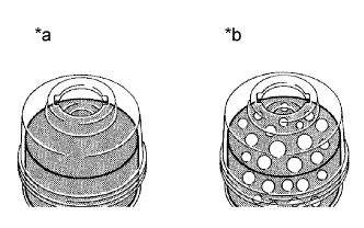
Text in Illustration *a Normal *b Abnormal Check for foaming or emulsification.
Especially, if the system has to be bled twice because of foaming or emulsification, check for fluid leakage in the system.
-
Check the fluid level.
-
-
CHECK POWER STEERING FLUID LEAKAGE
-
INSPECT AND ADJUST FRONT WHEEL ALIGNMENT