STEERING GEAR DISASSEMBLY

-
FIX RACK & PINION POWER STEERING GEAR ASSEMBLY
-
Using a union nut wrench, remove the 2 turn pressure tubes.
-
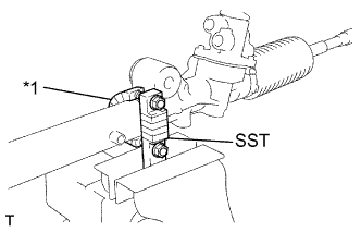
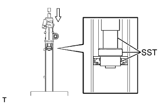
Text in Illustration *1 Vinyl Tape Using the SST, fix the gear assembly, between aluminum plates in a vise, as shown in the illustration.
- SST
- 09612-00012
-
-
REMOVE TIE ROD END SUB-ASSEMBLY LH
-
Place matchmarks on the tie rod end, lock nut and rack end.
-
Loosen the lock nut, remove the tie rod end and lock nut.
-
-
REMOVE TIE ROD END SUB-ASSEMBLY RH
Tech Tips
Remove the RH side by the same procedures with the LH side.
-
REMOVE STEERING RACK BOOT NO.1 CLAMP
-
Using pliers and a screwdriver, loosen the clamp.
-
Remove the clip and boot.
Note
Be careful not to damage the boot.
Tech Tips
Mark the RH and LH boots.
-
-
REMOVE STEERING RACK BOOT NO.2 CLAMP
Tech Tips
Remove the No.2 side by the same procedures with the No.1 side.
-
REMOVE STEERING RACK BOOT NO.2
-
REMOVE STEERING RACK BOOT NO.1
-
REMOVE STEERING RACK END SUB-ASSEMBLY
-
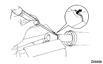
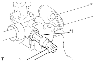
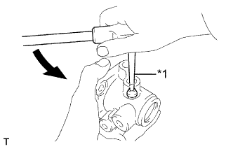
Using a screwdriver and a hammer, stake back the washer.
Note
Avoid any impact to the steering rack.
-
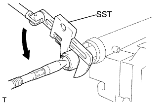
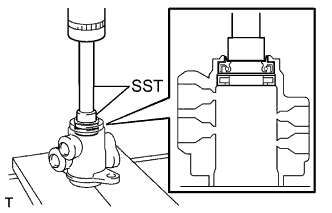
Using a spanner to hold the steering rack steady, and using SST, remove the rack end.
- SST
- 09922-10010
Note
Use SST 09922-10010 in the direction shown in the illustration.
-
Remove the washer.
-
Employ the same manner described above to the other side.
Tech Tips
Mark the RH and LH rack ends.
-
-
REMOVE RACK GUIDE
-
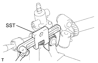
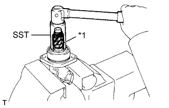
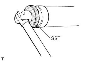
Using SST, remove the lock nut.
- SST
- 09922-10010
Note
Use SST 09922-10010 in the direction shown in the illustration.
-
Text in Illustration *1 Hexagon Wrench Using a hexagon wrench (24 mm), remove the rack guide spring cap.
-
Remove the spring and rock guide.
-
-
REMOVE POWER STEERING CONTROL VALVE
-
Remove the 2 bolts.
-
Pull out the control valve assembly with the control valve housing.
-
Remove the O-ring.
-
Carefully mount the control valve assembly in a soft jaw vise.
-
Text in Illustration *1 Vinyl Tape Using SST, remove the bearing guide nut.
- SST
- 09631-20060
Note
Be careful not to damage the oil seal lip.
-
Remove the O-ring.
-
Remove the dust cover.
-
Using SST and a hammer, drive out the oil seal from the bearing guide nut.
- SST
- 09950-60010 ( 09951-00300 )
- 09950-70010 ( 09951-07100 )
-
Text in Illustration *1 Vinyl Tape Wind vinyl tape to the control valve shaft.
-
Using a plastic hammer, tap out the valve assembly with the bearing guide nut from the control valve housing.
Note
Be careful not to damage the oil seal lip.
-
Using a screwdriver, remove the 4 teflon rings from the control valve assembly.
Note
Be careful not to damage the grooves for the ring.
-
Text in Illustration *1 Screw Extractor Using a screw extractor, remove the union seat from the control valve housing.
-
-
REMOVE POWER STEERING CONTROL VALVE UPPER OIL SEAL
-
Using SST, press out the bearing and oil seal from the control valve housing.
- SST
- 09950-60010 ( 09951-00250 )
- 09950-70010 ( 09951-07150 )
-
-
REMOVE CYLINDER END STOPPER
-
Using SST, remove the stopper.
- SST
- 09631-36010
-
Remove the O-ring from the stopper.
-
-
REMOVE POWER STEERING RACK
-
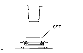
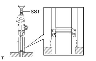
Using SST, press out the steering rack and oil seal.
- SST
- 09612-24014 ( 09612-10061 )
Note
Take care not to drop the rack.
-
Remove the oil seal from the rack.
-
-
REMOVE POWER STEERING CYLINDER TUBE OIL SEAL
-
Using SST, press out the oil seal and spacer.
- SST
- 09950-60010 ( 09951-00310, 09951-00300, 09952-06010 )
- 09950-70010 ( 09951-07360 )
-
-
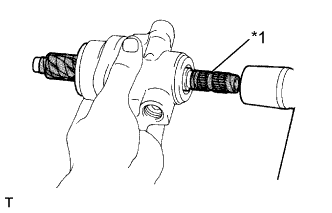
INSPECT POWER STEERING RACK
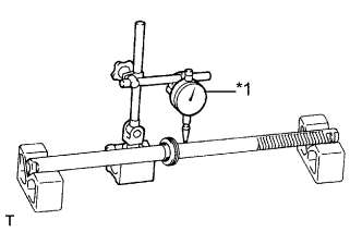
Text in Illustration *1 Dial Indication
-
Using a dial indicator, check the rack for runout and for teeth wear and damage.
Maximum runout 0.15 mm (0.006 in.) -
Check the back surface for wear and damage.
-
-
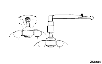
INSPECT TIE ROD END SUB-ASSEMBLY LH
-
Flip the ball joint stud back and forth 5 times as shown in the figure, before installing the nut.
-
Using a torque wrench, turn the nut continuously at a rate of 2 - 4 seconds per 1 turn and take the torque reading on the 5th turn.
Torque(Turning) 0.29 - 2.45 N*m (2.9 - 24.9 kgf*cm, 2.57 - 21.7 in.*lbf)
-
-
INSPECT TIE ROD END SUB-ASSEMBLY RH
Tech Tips
Inspect the RH side by the same procedures with the LH side.
-
REMOVE POWER PISTON OIL SEAL
-
Using a screwdriver, remove the teflon ring and oil seal from the steering rack.
Note
Be careful not to damage the groove for the ring.
-