STEERING GEAR REMOVAL

Tech Tips
COMPONENTS: Click here
-
PRECAUTION (W/ SRS AIRBAG)
-
SEPARATE BATTERY NEGATIVE TERMINAL (W/ SRS AIRBAG)
-
PLACE FRONT WHEELS FACING STRAIGHT AHEAD
-
REMOVE HORN BUTTON ASSEMBLY (W/ SRS AIRBAG)
-
REMOVE STEERING WHEEL ASSEMBLY (W/ SRS AIRBAG)
-
REMOVE STEERING COLUMN COVER LWR (W/ SRS AIRBAG)
-
Remove the clip, 2 screws and steering column cover LWR.
-
-
REMOVE TURN SIGNAL SWITCH ASSEMBLY (W/ SRS AIRBAG)
-
REMOVE SPIRAL CABLE SUB-ASSEMBLY (W/ SRS AIRBAG)
-
REMOVE FRONT WHEEL
-
SEPARATE TIE ROD END SUB-ASSEMBLY LH
-
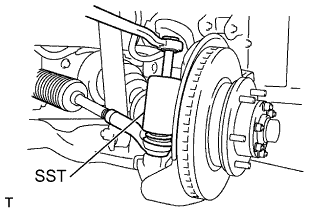
Remove the cotter pin and nut.
-
Using SST, disconnect the tie rod end from the steering knuckle arm.
- SST
- 09610-20012
-
-
SEPARATE TIE ROD END SUB-ASSEMBLY RH
Tech Tips
Remove the RH side by the same procedures with the LH side.
-
REMOVE STEERING TORQUE SHAFT ASSEMBLY
-
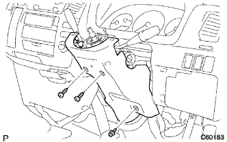
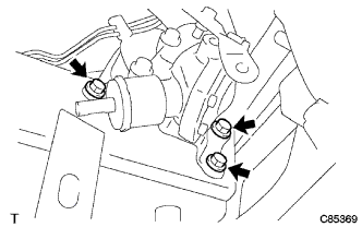
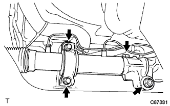
Remove the 3 bolts, steering link protector UPR and steering link protector LWR.
-
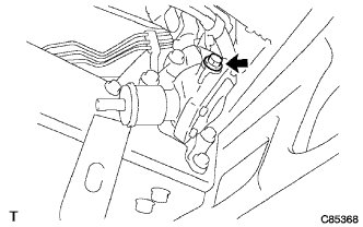
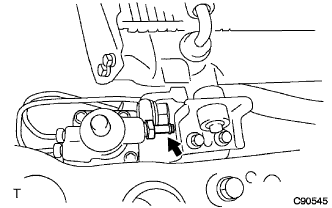
Remove the 2 bolts.
-
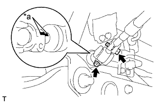
Text in Illustration *a Matchmark Shift the sliding yoke and place the matchmarks to the sliding yoke and steering gear.
-
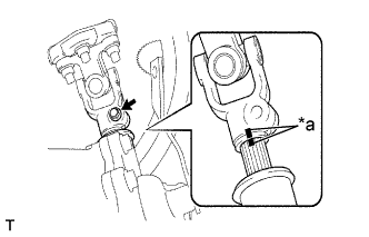
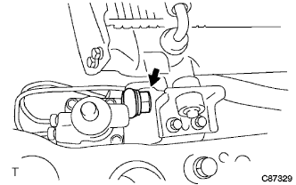
Remove the bolt.
-
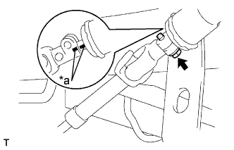
Text in Illustration *a Matchmark Shift the torque shaft and place the matchmarks to the torque shaft and bevel gear.
-
Remove the torque shaft.
-
-
REMOVE STEERING SLIDING YOKE SUB-ASSEMBLY
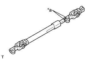
Text in Illustration *a Matchmark
-
Place matchmarks on the sliding yoke and torque shaft.
-
Remove the sliding yoke from the torque shaft.
-
Remove the shaft cover.
-
-
REMOVE STEERING BEVEL GEAR ASSEMBLY
-
Remove the bolt on the gear side (lower side) of the sliding yoke.
-
Text in Illustration *a Matchmark Shift the sliding yoke and place the matchmarks to the sliding yoke and bevel gear.
-
Disconnect the sliding yoke from the bevel gear.
-
Remove the bolt and disconnect the bracket of the transmission control cable (LHD steering position type only).
-
Remove the bolt and disconnect the bracket of the parking brake cable (RHD steering position type only).
-
Remove the 3 bolts and the bevel gear with bracket.
-
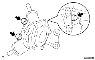
Remove the 3 bolts and housing bracket from bevel gear.
-
-
INSPECT TOTAL PRELOAD
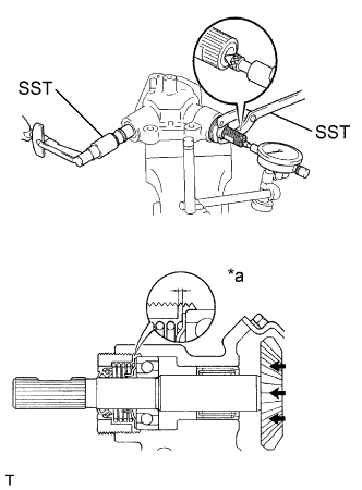
Text in Illustration *a Movement amount of the Bevel Gear No. 2
-
Using SST, turn the bevel gears 5 or 6 times to settle them down.
- SST
- 09612-24014 ( 09616-10010 )
- 09960-10010 ( 09962-01000, 09963-00350 )
-
While measuring the rotation torque of the bevel gear No. 1 with SST and a torque wrench, measure the movement amount in the shaft direction with a dial indicator. inspect both measured values are within the specification range.
Preload (turning) 0.15 - 0.39 N*m (1.5 - 4.0 kgf*cm, 1.30 - 3.47 in.*lbf) Axial movement amount (bevel gear No. 2) 0.36 mm (0.0143 in.) or less Tech Tips
The movement amount in the axial direction of the bevel gear No. 2 is the dimension of the illustration.
-
-
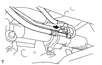
SEPARATE STEERING GEAR OUTLET RETURN TUBE
-
Remove the bolt (LHD steering position type only).
-
Remove the clip and disconnect the return hose.
-
Remove the return tube.
-
-
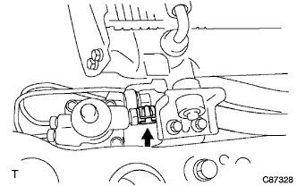
SEPARATE PRESSURE FEED TUBE ASSEMBLY
-
Remove the union bolt and gasket, and disconnect the feed tube.
-
-
REMOVE RACK & PINION POWER STEERING GEAR ASSEMBLY
-
Remove the 2 bolts, rack bracket and grommet.
-
Remove the bolt, washer and nut.
-
Remove the PS gear assembly.
-