BRAKE BOOSTER INSTALLATION

-
INSTALL BRAKE BOOSTER ASSEMBLY
-
Install the brake booster with the 4 nuts.
- Torque:
- 13 N*m { 130 kgf*cm, 9 ft.*lbf }
-
Install the push rod clevis and lock nut.
-
Install the master cylinder push rod pin and clip.
-
-
INSTALL BRAKE PEDAL BRACKET ASSEMBLY
-
Install the brake pedal bracket assembly with the 2 bolts and nuts.
- Torque:
- 31 N*m { 300 kgf*cm, 22 ft.*lbf }
-
Connect the vacuum hose.
-
Connect the brake tube clamp.
-
Install the check connector. (RHD STEERING POSITION TYPE)
-
Install the turn signal flasher with the bolt. (RHD STEERING POSITION TYPE)
-
Install the airbag sensor assembly with the 3 bolts. (w/ Airbag)
- Torque:
- 20 N*m { 200 kgf*cm, 14 ft.*lbf }
-
Install the 3 clutch pedal bracket mount bolt.
- Torque:
- 19 N*m { 185 kgf*cm, 14 ft.*lbf }
-
-
INSTALL BRAKE MASTER CYLINDER SUB-ASSEMBLY
-
INSTALL INSTRUMENT PANEL SUB-ASSEMBLY
-
CHECK AND ADJUST BRAKE PEDAL HEIGHT
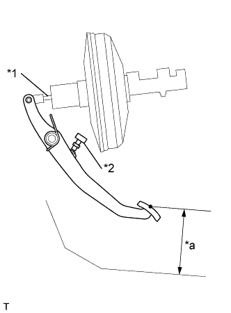
Text in Illustration *1 Push Rod *2 Stop Light Switch *a Pedal Height
-
Inspect brake pedal height.
Pedal height from asphalt sheet 143.9 - 153.9 mm (5.665 - 6.059 in.) -
Adjust brake pedal height.
-
Remove the instrument finish panel lower.
-
Disconnect the connector from the stop light switch.
-
Loosen the stop light switch lock nut and remove the stop light switch.
-
Loosen the clevis lock nut.
-
Adjust the pedal height by turning the pedal push rod.
-
Tighten the push rod lock nut.
- Torque:
- 26 N*m { 265 kgf*cm, 19 ft.*lbf }
-
Install the stop light switch.
-
Connect the connector to the stop light switch.
-
Push the brake pedal in 5 - 15 mm (0.20 - 0.59 in.), turn the stop light switch to lock the nut in the position where the stop light goes off.
-
After installation, push the brake pedal in 5 - 15 mm (0.20 - 0.59 in.), check that stop light lights up.
-
-
-
CHECK BRAKE PEDAL FREE PLAY
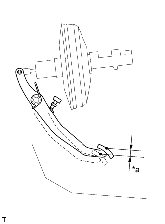
Text in Illustration *a Pedal Free Play
-
Stop the engine and depress the brake pedal several times until there is no more vacuum left in the booster.
-
Push in the pedal until the beginning of the resistance is felt. Measure the distance, as shown.
Pedal free play 1 - 6 mm (0.04 - 0.24 in.) If incorrect, check the stop light switch clearance.
If the clearance is OK, then troubleshoot the brake system.
Stop light switch clearance 0.5 - 2.4 mm (0.020 - 0.094 in.)
-
-
CHECK BRAKE PEDAL RESERVE DISTANCE
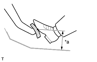
Text in Illustration *a Pedal Reserve Distance
-
Release the parking brake lever.
With engine running, depress the pedal and measure the pedal reserve distance, as shown.
Pedal reserve distance from asphalt sheet at 490 N (50 kgf, 110.2 lbf) Europe DYNA 100 More than 59 mm (2.32 in.) DYNA 150 More than 51 mm (2.01 in.) Australia DYNA 100 More than 69 mm (2.72 in.) DYNA 150 More than 59 mm (2.32 in.) General DYNA 100 More than 69 mm (2.72 in.) DYNA 150 (LY235R - TLMGS, TLMKS) More than 69 mm (2.72 in.) (Others) More than 59 mm (2.32 in.) If incorrect, troubleshoot the brake system.
-