ANTI-LOCK BRAKE SYSTEM TS and CG Terminal Circuit
DESCRIPTION
In the sensor check mode, a malfunction of the speed sensor that cannot be judged when the vehicle is stopped is judged while driving.
Transition to the sensor check mode can be performed by connecting terminals Ts and CG of the DLC3 and turning the ignition switch from OFF to ON.
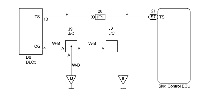
WIRING DIAGRAM
INSPECTION PROCEDURE
PROCEDURE
-
INSPECT DLC3
-

Text in Illustration *a Front view of DLC3 Turn the ignition switch ON.
-
Measure voltage between terminals Ts and CG of DLC3.
OK Voltage: 10 - 14 V
OK 
CHECK ABS WARNING LIGHT Click here
NG 
-
-
CHECK HARNESS AND CONNECTOR (DLC3 - SKID CONTROL ECU, DLC3 - BODY GROUND)
-
Check for open and short circuit in harness and connector between terminal Ts of DLC3 and skid control ECU, and CG of the DLC3 and body ground Click here.
NG 
REPAIR OR REPLACE HARNESS OR CONNECTOR
OK 
CHECK AND REPLACE SKID CONTROL ECU ASSEMBLY
-
-
CHECK ABS WARNING LIGHT
- SST
- 09843-18040
-
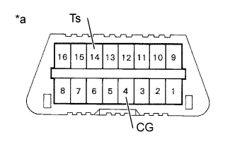
Text in Illustration *a Front view of DLC3 Using SST, connect the terminals Ts and CG of the DLC3.
-
Check the ABS warning light.
OK ABS warning light blinking
OK
NO PROBLEM
NG
CHECK AND REPLACE SKID CONTROL ECU ASSEMBLY