ANTI-LOCK BRAKE SYSTEM, Diagnostic DTC:C1251/51

| DTC Code | DTC Name |
|---|---|
| C1251/51 | Open in Pump Motor Circuit |
DESCRIPTION
| DTC No. | DTC Detecting Condition | Trouble Area |
|---|---|---|
| C1251/51 | When the ABS actuator pump drive motor is not operating normally. |
|
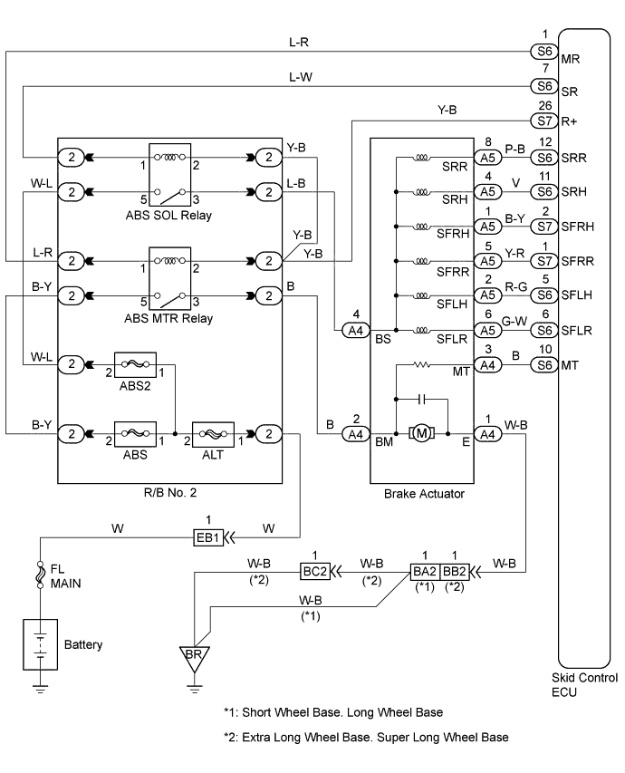
WIRING DIAGRAM
INSPECTION PROCEDURE
PROCEDURE
-
INSPECT BRAKE ACTUATOR ASSEMBLY (PUMP MOTOR OPERATION)
-
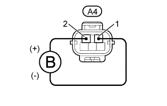
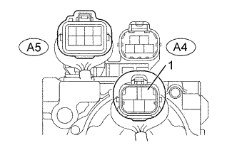
Disconnect the connector (A4) from the brake actuator.
-
Connect the positive (+) lead from the battery to BM (2) terminal and negative (-) lead to GND (1) terminal of the brake actuator, check that the pump motor is operated.
OK The running sound of the pump motor should be heard.
NG 
CHECK AND REPLACE BRAKE ACTUATOR ASSEMBLY
OK 
-
-
CHECK HARNESS AND CONNECTOR (ABS MOTOR RELAY - BRAKE ACTUATOR - SKID CONTROL ECU)
-
Check for open and short circuit in harness and connector between ABS motor relay, brake actuator and skid control ECU Click here.
NG
REPAIR OR REPLACE HARNESS OR CONNECTOR
OK
-
-
CHECK CONTINUITY (GND OF BRAKE ACTUATOR - BODY GROUND)
-
Measure resistance between terminals GND (A4 - 1) of brake actuator connector and body ground.
OK Resistance: 1 Ω or less
NG
REPAIR OR REPLACE HARNESS OR CONNECTOR
OK 
CHECK AND REPLACE SKID CONTROL ECU ASSEMBLY
-