ANTI-LOCK BRAKE SYSTEM, Diagnostic DTC:C1241/41

| DTC Code | DTC Name |
|---|---|
| C1241/41 | Low Battery Positive Voltage or Abnormally High Battery Positive Voltage |
DESCRIPTION
| DTC No. | DTC Detecting Condition | Trouble Area |
|---|---|---|
| C1241/41 |
|
|
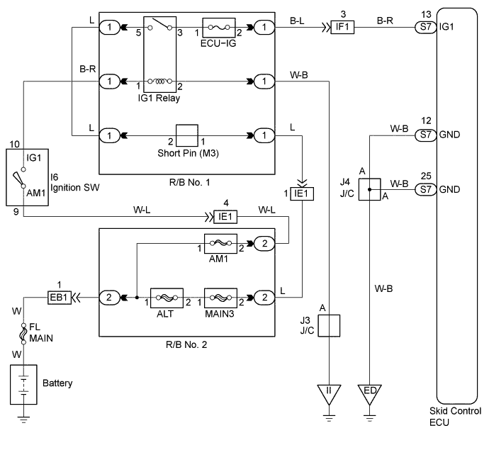
WIRING DIAGRAM
INSPECTION PROCEDURE
PROCEDURE
-
INSPECT FUSES (ECU-IG OF R/B No. 1)
-
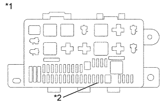
Text in Illustration *1 R/B No. 1 *2 ECU-IG Remove ECU-IG fuse from the R/B No. 1.
-
Check continuity of ECU-IG fuse.
OK Continuity
NG 
INSPECT FOR SHORT CIRCUIT IN ALL HARNESS AND COMPONENTS CONNECTED TO ECU-IG FUSE
OK 
-
-
INSPECT BATTERY (TERMINAL VOLTAGE)
-
Check the battery positive voltage.
OK Voltage: 10 - 14 V
NG
CHECK CHARGING SYSTEM
OK
-
-
CHECK VOLTAGE OF ECU IG POWER SOURCE
In case of using the intelligent tester:
-
Select the DATALIST mode on the intelligent tester.
-
Check the voltage condition output from the ECU displayed on the intelligent tester.
OK "Normal" is displayed. In case of not using the intelligent tester:
-
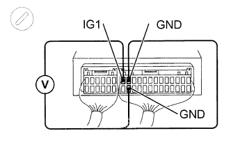
Remove the skid control ECU with connectors still connected.
-
Turn the ignition switch ON, measure voltage between terminals IG1 and GND of skid control ECU connector.
OK Voltage: 10 - 14 V
OK
CHECK AND REPLACE SKID CONTROL ECU ASSEMBLY
NG
-
-
CHECK CONTINUITY (GND OF SKID CONTROL ECU -BODY GROUND)
-
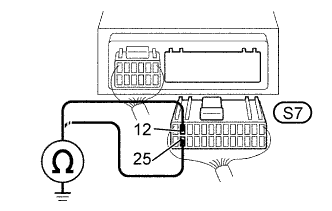
Disconnect the connector from the skid control ECU.
-
Measure resistance between terminals GND (S7 - 12, 25) of skid control ECU harness side connector and body ground.
OK Resistance: 1 Ω or less
NG
REPAIR OR REPLACE HARNESS OR CONNECTOR
OK
-
-
CHECK HARNESS AND CONNECTOR (ECU-IG FUSE - SKID CONTROL ECU)
-
Check for open and short circuit in harness and connector between ECU-IG fuse and skid control ECU Click here.
NG
REPAIR OR REPLACE HARNESS OR CONNECTOR
OK 
CHECK AND REPLACE SKID CONTROL ECU ASSEMBLY
-