ANTI-LOCK BRAKE SYSTEM, Diagnostic DTC:C0226/21, C0236/22, C0246/23

| DTC Code | DTC Name |
|---|---|
| C0226/21 | SFR Solenoid Circuit |
| C0236/22 | SFL Solenoid Circuit |
| C0246/23 | SRR Solenoid Circuit |
DESCRIPTION
This solenoid goes on when signals are received from the ECU and controls the pressure acting on the wheel cylinders thus controlling the braking force.
| DTC No. | DTC Detecting Condition | Trouble Area |
|---|---|---|
| C0226 / 21 | Conditions 1. and 2. continue for 0.05 seconds or more.
|
|
| C0236 / 22 | Conditions 1. and 2. continue for 0.05 seconds or more.
|
|
| C0246 / 23 | Conditions 1. and 2. continue for 0.05 seconds or more.
|
|
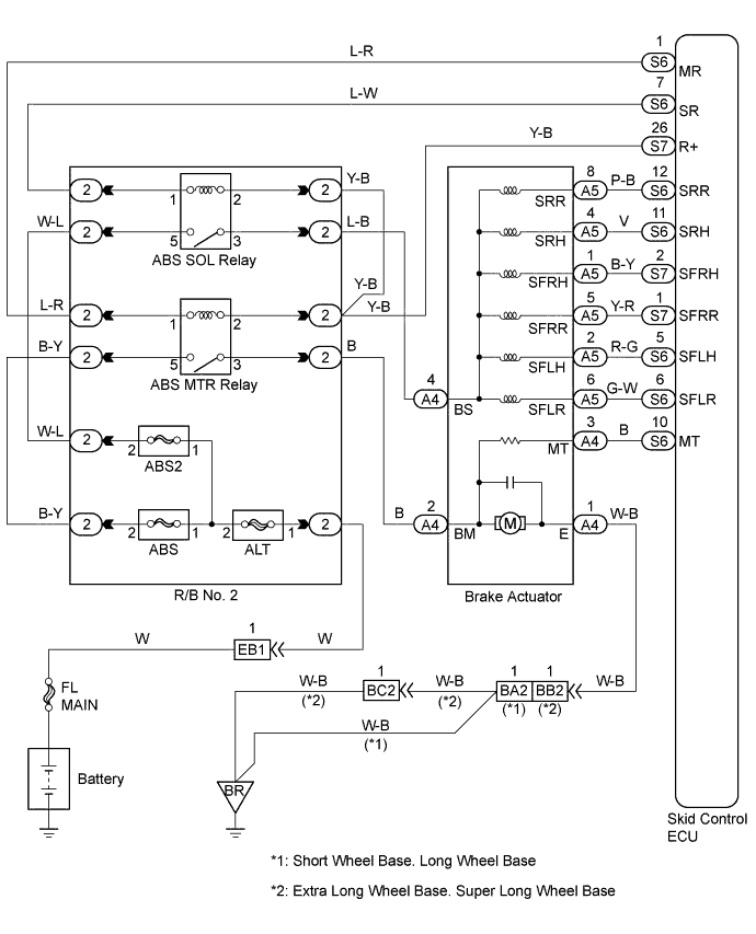
WIRING DIAGRAM
INSPECTION PROCEDURE
PROCEDURE
-
INSPECT BRAKE ACTUATOR ASSEMBLY
-
Disconnect the 2 connectors from the brake actuator.
-
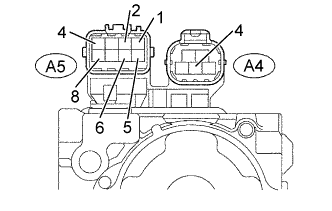
Check continuity between terminal A4 - 4 and A5 - 1, 2, 4, 5, 6 and 8 of brake actuator.
OK Continuity Tech Tips
Resistance of each solenoid
SFRH (A5-1), SFLH (A5-2), SRH (A5-4): 8.1 - 9.1 Ω
SFRR (A5-5), SFLR (A5-6), SRR (A5-8): 4.0 - 4.6 Ω
NG 
REPLACE BRAKE ACTUATOR ASSEMBLY
OK 
-
-
CHECK HARNESS AND CONNECTOR (BRAKE ACTUATOR - SKID CONTROL ECU)
-
Check for open and short circuit in harness and connector between each solenoid and skid control ECU Click here.
NG
REPAIR OR REPLACE HARNESS OR CONNECTOR
OK
-
-
CHECK SKID CONTROL ECU TERMINAL VOLTAGE (SR TERMINAL)
-
Remove the skid control ECU with connectors still connected.
-
Turn the ignition switch ON, measure between terminal SR and GND.
OK Voltage: 1 V or less
NG
CHECK AND REPAIR HARNESS AND ABS SOLENOID RELAY
OK
-
-
CHECK RECONFIRM DTC
-
Check DTC on page Click here.
A Malfunction Code B Normal Code
B
NO PROBLEM
A
-
-
CHECK CONTACT CONDITION (EACH CONNECTION)
NG
CHECK AND REPAIR HARNESS AND CONNECTOR
OK 
CHECK AND REPLACE SKID CONTROL ECU ASSEMBLY