ANTI-LOCK BRAKE SYSTEM, Diagnostic DTC:C0273/13, C0274/14

| DTC Code | DTC Name |
|---|---|
| C0273/13 | Open in ABS Motor Relay Circuit |
| C0274/14 | Short to B+ in ABS Motor Relay Circuit |
DESCRIPTION
The ABS motor relay supplies power to the ABS pump motor. While the ABS is activated, the ECU switches the motor relay ON and operates the ABS pump motor.
| DTC No. | DTC Detecting Condition | Trouble Area |
|---|---|---|
| C0273/13 | Conditions 1. or 2. continue for 0.2 seconds or more.
|
|
| C0274/14 | Conditions 1. and 2. continue for 4 seconds or more.
|
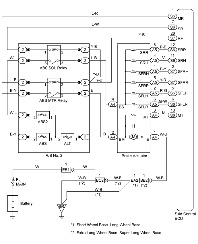
WIRING DIAGRAM
INSPECTION PROCEDURE
Tech Tips
Start the inspection from step 1 in case of using the intelligent tester and start from step 2 in case of not using intelligent tester.
PROCEDURE
-
DO ACTIVE TEST OF INTELLIGENT TESTER (ABS MOTOR RELAY OPERATION)
-
Select the ACTIVE TEST mode on the intelligent tester.
-
Check the operation sound of the ABS motor relay when operating it with the intelligent tester.
OK The operation sound of the pump motor should be heard.
OK 
CHECK CONTINUITY (TERMINAL 5 OF R/B No. 2-MT OF SKID CONTROL ECU) Click here
NG 
-
-
CHECK TERMINAL VOLTAGE (TERMINAL 5 OF R/B No. 2)
-
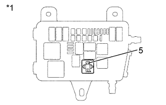
Text in Illustration *1 R/B No. 2 Remove the ABS motor relay from R/B No. 2.
-
Measure voltage between terminal 5 of R/B No. 2 (for ABS motor relay) and body ground.
OK Voltage: 10 - 14 V
NG
INSPECT FUSE (ABS OF R/B No. 2) Click here
OK
-
-
INSPECT ABS MOTOR RELAY
-
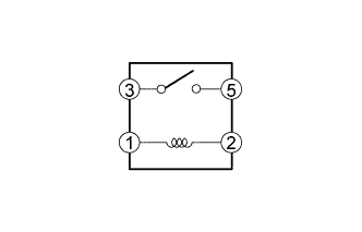
Check continuity between each terminal of ABS motor relay.
OK Terminals 1 and 2 Continuity (Reference value 80 Ω) Terminals 3 and 5 Open -
Apply battery positive voltage between terminals 1 and 2.
-
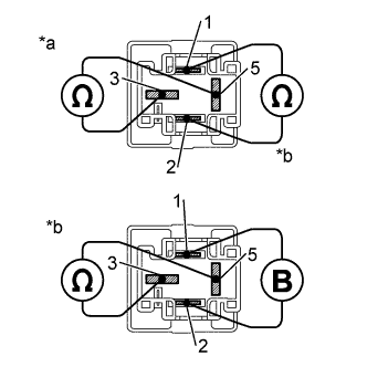
Text in Illustration *a Open *b Continuity Check continuity between terminals 3 and 5 of ABS motor relay.
OK Terminals 3 and 5 Continuity
NG 
REPLACE ABS MOTOR RELAY
OK
-
-
CHECK CONTINUITY (TERMINAL 5 OF R/B No. 2-MT OF SKID CONTROL ECU)
-
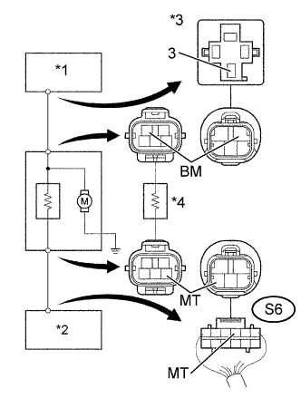
Text in Illustration *1 ABS MTR Relay *2 Skid control ECU *3 R/B No. 2 *4 Brake Actuator Disconnect the connector (S6) from the skid control ECU.
-
Check continuity between terminal 3 of R/B No. 2 (for ABS MTR relay) and terminal MT (S6 - 10) of skid control ECU harness side connector.
OK Continuity Tech Tips
There is resistance of 33 Ω between terminals BM and MT of the brake actuator.
NG
REPAIR OR REPLACE HARNESS, CONNECTOR OR RAKE ACTUATOR
OK
-
-
CHECK HARNESS AND CONNECTOR (ABS MOTOR RELAY - SKID CONTROL ECU)
-
Check for open and short circuit in harness and connector between ABS motor relay and skid control ECU Click here.
NG
REPAIR OR REPLACE HARNESS OR CONNECTOR
OK
-
-
CHECK RECONFIRM DTC
-
Check DTC on page Click here.
A Malfunction Code B Normal Code
B
NO PROBLEM
A
-
-
CHECK CONTACT CONDITION
OK
CHECK AND REPLACE SKID CONTROL ECU ASSEMBLY
NG 
CHECK AND REPAIR HARNESS AND CONNECTOR
-
INSPECT FUSE (ABS OF R/B No. 2)
-
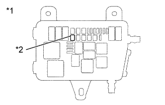
Text in Illustration *1 R/B No. 2 *2 ABS Remove ABS fuse from the R/B No. 2.
-
Check continuity of ABS fuse.
OK Continuity
NG
REPLACE FUSE
OK
CHECK AND REPAIR HARNESS AND CONNECTOR
-