ANTI-LOCK BRAKE SYSTEM, Diagnostic DTC:C0210/33, C0215/34, C1238/38, C1239/39

| DTC Code | DTC Name |
|---|---|
| C0210/33 | Rear Speed Sensor RH Circuit |
| C0215/34 | Rear Speed Sensor LH Circuit |
| C1238/38 | Foreign Object is Attached on Tip of Rear Speed Sensor RH |
| C1239/39 | Foreign Object is Attached on Tip of Rear Speed Sensor LH |
DESCRIPTION
Refer to DTC C0200/31, C0205/32, C1238/38, C1239/39 on page Click here.
| DTC No. | DTC Detecting Condition | Trouble Area |
|---|---|---|
| C0210/33 C0215/34 |
Detection of any of conditions 1. through 3.:
|
|
| C1238/38 C1239/39 |
When the vehicle speed is higher than 20 km/h (12 mph) and noise on the abnormal wheel sensor signal continues for 5 seconds or more. |
|
Tech Tips
DTC No. C0210/33, C1238/38 is the right rear speed sensor.
DTC No. C0215/34, C1239/39 is the left rear speed sensor.
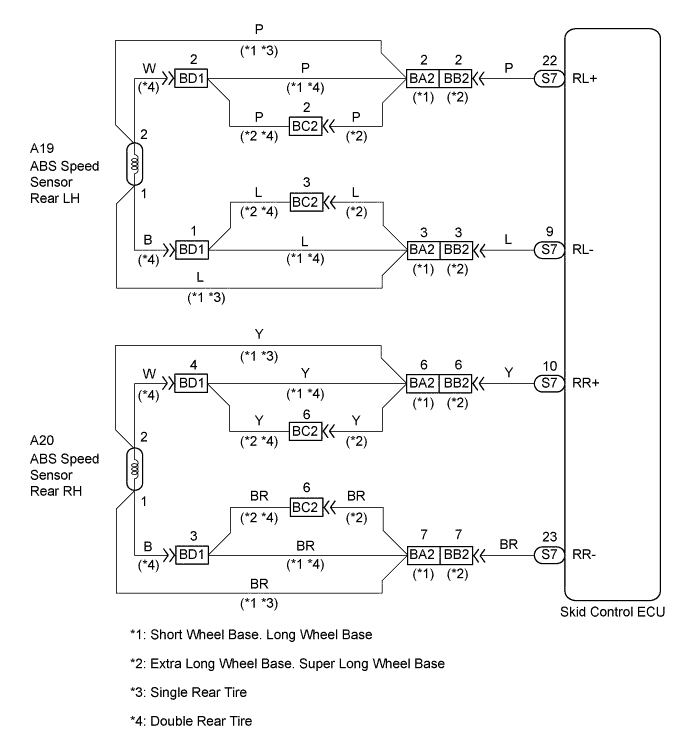
WIRING DIAGRAM
INSPECTION PROCEDURE
Tech Tips
Start the inspection from step 1 in case of using intelligent tester and start from step 2 in case of not using intelligent tester.
PROCEDURE
-
READ VALUE OF REAR SPEED SENSOR
-
Select the DATALIST mode on the intelligent tester.
-
Check that there is no difference between the speed value output from the speed sensor displayed by the intelligent tester and the speed value displayed by the speedometer when driving the vehicle.
OK There is almost no difference from the displayed speed value. Tech Tips
There is tolerance of +/- 10% in the speedometer indication.
OK 
INSPECT SPEED SENSOR AND SENSOR ROTOR SERRATIONS INSTALLATION Click here
NG 
-
-
INSPECT REAR SPEED SENSOR
-
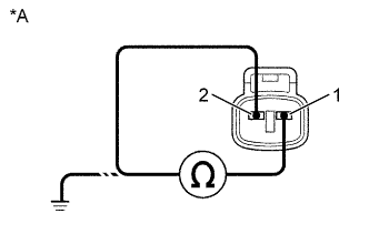
Text in Illustration *A Double Tire Type Skid control Sensor (Double Tire Type):
-
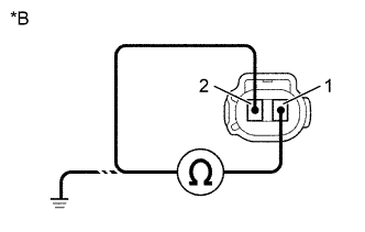
Text in Illustration *B Single Tire Type Speed sensor rear (Single Tire Type):
-
Make sure that there is no looseness at the connector lock part and connecting part of the connector.
-
Disconnect the speed sensor connector.
-
Measure resistance between terminals 1 and 2 of speed sensor connector.
OK Resistance: 0.85 - 1.25 kΩ (Double Tire Type) 1.0 - 1.4 kΩ (Single Tire Type) -
Measure resistance between terminals 1 and 2 of speed sensor connector and body ground.
OK Resistance: 1 MΩ or higher
-
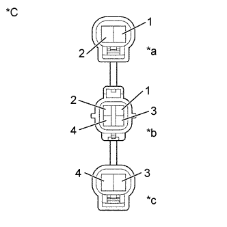
Text in Illustration *C Double Tire Type *a Connector (LH) *b Connector 1 *c Connector (RH) Skid control Sensor Wire (Double Tire Type):
-
-
Make sure that there is no looseness at the connector lock part and connecting part of the connector.
-
Measure resistance between terminal 1 of connector 1 and terminal 1 of connector (LH).
-
Measure resistance between terminal 2 of connector 1 and terminal 2 of connector (LH).
-
Measure resistance between terminal 3 of connector 1 and terminal 3 of connector (RH).
-
Measure resistance between terminal 4 of connector 1 and terminal 4 of connector (RH).
OK Resistance: 1 Ω or lower -
Measure resistance between terminals 1, 2, 3, and 4 of speed sensor connector 1 and body ground.
OK Resistance: 10 MΩ or higher A OK B NG (Double tire type, Skid control sensor) C NG (Double tire type, Skid control sensor wire) D NG (Single tire type, Speed sensor rear RH) E NG (Single tire type, Speed sensor rear LH)
B 
REPLACE SKID CONTROL SENSOR
C
REPLACE SKID CONTROL SENSOR WIRE
D
REPLACE SPEED SENSOR REAR RH
E
REPLACE SPEED SENSOR REAR LH
A
-
-
CHECK HARNESS AND CONNECTOR (REAR SPEED SENSOR-SKID CONTROL ECU)
-
Check for open and short circuit in harness and connector between each speed sensor and skid control ECU connector Click here.
NG
REPAIR OR REPLACE HARNESS AND CONNECTOR
OK
-
-
INSPECT REAR SPEED SENSOR INSTALLATION
-
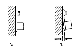
Text in Illustration *a OK *b NG Check the speed sensor installation.
OK The installation bolt is tightened properly and there is no clearance between the sensor and front steering knuckle. - Torque:
- 8.0 N*m { 82 kgf*cm, 71 in.*lbf }
A OK B NG (Double tire type, Skid control sensor) C NG (Single tire type, Speed sensor rear RH) D NG (Single tire type, Speed sensor rear LH) Note
Check the speed sensor signal last Click here.
B
REPLACE SKID CONTROL SENSOR
C
REPLACE SPEED SENSOR REAR RH
D
REPLACE SPEED SENSOR REAR LH
A
-
-
INSPECT SPEED SENSOR AND SENSOR ROTOR SERRATIONS INSTALLATION
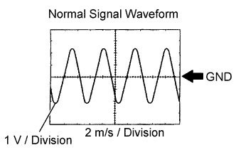
(REFERENCE) INSPECTION USING OSCILLOSCOPE
-
Connect the oscilloscope to the terminals RR+, RR- and and GND of the skid control ECU.
-
Drive the vehicle at about 30 km/h (19 mph), and check the signal waveform.
Tech Tips
-
As the vehicle speed (wheel revolution speed) increases, a cycle of the waveform becomes shorter and the fluctuation in the output voltage becomes greater.
-
When noise is identified in the waveform on the oscilloscope, error signals are generated due to the speed sensor rotor's scratches, looseness or foreign matter deposited on it.
-
OK
CHECK AND REPLACE SKID CONTROL ECU ASSEMBLY
NG
-
-
INSPECT SPEED SENSOR ROTOR AND SENSOR TIP
-
Remove the rear speed sensor Click here.
-
Check the sensor tip.
OK No scratches or foreign objects on the sensor tip.
NG
CLEAN OR REPLACE SPEED SENSOR
OK
-
-
INSPECT SPEED SENSOR ROTOR
-
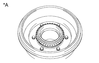
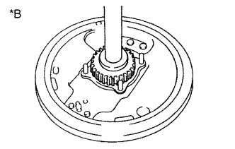
Remove the rear axle.
Text in Illustration *A Double Tire Type *B Single Tire Type
-
Double tire type (Just low):
-
Double tire type (Full just low):
-
Single tire type:
-
-
Check the sensor rotor serrations
OK No scratches, missing teeth or foreign objects. Tech Tips
If foreign matter is attached, remove it and after reassembling, check the output waveform.
Note
Check the speed sensor signal last Click here.
NG
CLEAN OR REPLACE SPEED SENSOR ROTOR
OK 
CHECK AND REPLACE SKID CONTROL ECU ASSEMBLY
-