ANTI-LOCK BRAKE SYSTEM, Diagnostic DTC:Always ON

| DTC Code | DTC Name |
|---|---|
| Always ON | Malfunction in ABS ECU |
DESCRIPTION
Tech Tips
There is a case that intelligent tester cannot be used when ECU is abnormal.
| DTC No. | DTC Detecting Condition | Trouble Area |
|---|---|---|
| Always ON | Either of the following 1. 2. 3. or 4. is detected:
|
|
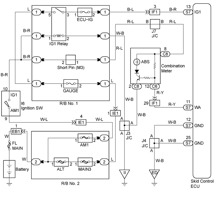
WIRING DIAGRAM
INSPECTION PROCEDURE
PROCEDURE
-
INSPECT BATTERY (TERMINAL VOLTAGE)
-
Check the battery positive voltage.
OK Voltage: 10 - 14 V
NG 
CHECK AND REPLACE CHARGING SYSTEM
OK 
-
-
CHECK SKID CONTROL ECU CONNECTOR SECURELY CONNECTED
NG
CONNECT CONNECTORS
OK
-
CHECK RECONFIRM DTC
-
Check DTC on Click here.
A Malfunction Code B Normal Code
B
REPAIR CIRCUIT INDICATED BY OUTPUT CODE
A
-
-
CHECK VOLTAGE OF ECU IG POWER SOURCE (IG1 TERMINAL VOLTAGE)
In case of using the intelligent tester:
-
Select the DATALIST mode on the intelligent tester.
-
Check the voltage condition output from the ECU displayed on the intelligent tester.
OK "Normal" is displayed. In case of not using the intelligent tester:
-
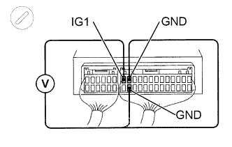
Remove the skid control ECU with connectors still connected.
-
Turn the ignition switch ON, measure voltage between terminals IG1 and GND of skid control ECU connector.
OK Voltage: 10 - 14 V
OK 
CHECK HARNESS AND CONNECTOR (DLC3 - SKID CONTROL ECU) Click here
NG
-
-
CHECK HARNESS AND CONNECTOR (BATTERY - SKID CONTROL ECU)
-
Check for open and short circuit in harness and connector between battery and skid control ECU Click here.
NG
CHECK AND REPAIR HARNESS AND CONNECTOR
OK
-
-
CHECK HARNESS AND CONNECTOR (DLC3 - SKID CONTROL ECU)
-
Check for short circuit in harness and connector between terminal Tc of DLC3 and skid control ECU Click here.
NG
REPAIR OR REPLACE HARNESS OR CONNECTOR
OK
-
-
CHECK ABS WARNING LIGHT
In case of using the intelligent tester:
-
Select the ACTIVE TEST mode on the intelligent tester.
-
Check that "ON" and "OFF" of the ABS warning light can be shown on the combination meter by the intelligent tester.
In case of not using the intelligent tester:
-
Turn the ignition switch OFF.
-
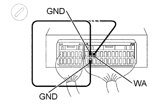
Remove the skid control ECU with connectors still connected.
-
Using a service wire, connect terminals WA and GND of the skid control ECU harness side connector.
-
Turn the ignition switch ON.
-
Check the ABS warning light goes off.
OK
CHECK AND REPLACE SKID CONTROL ECU ASSEMBLY
NG 
CHECK AND REPLACE COMBINATION METER ASSEMBLY
-