FRONT UPPER SUSPENSION ARM REMOVAL

-
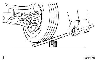
CHECK BALL JOINT LOOSENESS
-
Jack up the front side of the vehicle.
-
Put a lever under the wheel, use wood tip etc, as a fulcrum and lift the wheel up.
-
Then check the runout of the upper ball joint.
Maximum play 1.0 mm (0.03937 in.)
-
-
REMOVE FRONT WHEEL
-
REMOVE ENGINE SIDE COVER SUB-ASSEMBLY LH
-
Single cab:
Remove the 4 bolts and engine side cover sub-assembly LH.
-
Except Single cab:
Remove the 3 bolts and engine side cover sub-assembly LH.
-
-
REMOVE FRONT FLOOR SIDE APRON NO. 1 LH
-
Remove the 4 bolts and front side apron No. 1 LH.
-
-
REMOVE TILT CAB STAY ASSEMBLY (TILT CAB CAB TYPE)
-
Remove the 4 bolts and tilt cab stay assembly.
-
-
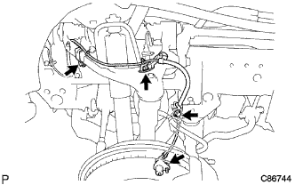
REMOVE ENGINE SIDE COVER BRACKET NO.1 LH
-
Remove the bolt, disconnect the heater bracket from the engine side cover bracket sub-assembly.
-
Remove the bolt, disconnect the transmission control cable bracket.
-
Remove the 2 bolts and engine side cover bracket sub-assembly.
-
-
REMOVE TORSION BAR SPRING LH
-
REMOVE FRONT SUSPENSION TORQUE ARM LH
-
SEPARATE SPEED SENSOR FRONT LH (w/ ABS)
-
Remove the 4 bolts, disconnect the speed sensor front LH from the front suspension arm sub-assembly upper LH.
-
-
REMOVE FRONT SUSPENSION ARM SUB-ASSEMBLY UPPER LH
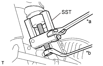
Text in Illustration *a Hold *b Turn
-
Support the front suspension lower arm LH on jack.
-
Remove the cotter pin and castle nut.
-
Using SST, disconnect the upper ball joint from the steering knuckle.
- SST
- 09628-62011
-
Remove the jack.
-
Remove the 3 bolts and front suspension upper arm LH.
-
-
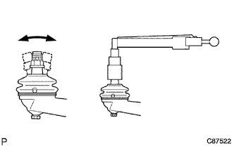
INSPECT FRONT SUSPENSION ARM SUB-ASSEMBLY UPPER LH
-
Flip the stud back and forth 5 times in the sliding direction, then rotate it continuously at the speed of 2 to 4 seconds per revolution and check that it turns smoothly.
-