TORSION BAR SPRING INSTALLATION

-
INSTALL FRONT SUSPENSION TORQUE ARM LH
-
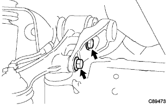
Install the 2 bolts and front suspension torque arm LH to the front suspension arm sub-assembly upper LH.
- Torque:
- 120 N*m { 1224 kgf*cm, 89 ft.*lbf }
-
-
TEMPORARILY TIGHTEN TORSION BAR SPRING LH
-
New torsion bar spring LH:
-
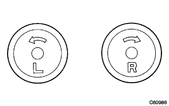
Identify left and right marks on the rear end of the torsion bar spring LH.
Note
The side the mark is on is to the rear.
-
Install the torsion bar dust cover LH to the torsion bar spring LH.
-
Apply MP grease to the spline at the both ends of the torsion bar spring LH.
-
Install the anchor arm sub-assembly LH to the frame sub-assembly.
-
Install the rear end of torsion bar spring LH to the anchor arm sub-assembly LH.
-
Install the tip of torsion bar spring LH to the front suspension torque arm LH.
-
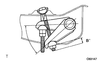
Note
Install the anchor arm sub-assembly LH so that dimension B' will be almost same as dimension B when it was removed.
-
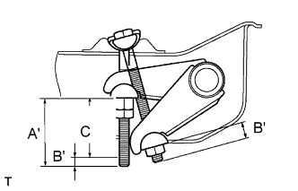
Tighten the adjust nut so that the dimension C at the figure will be the reference value.
Dimension C mm (in.) C= A' - B' Model C KDY220L-TBMDYW(3) 43 (1.693) KDY220R-TBMDYW 43 (1.693) KDY230L-PBMEYW3 41 (1.614) KDY230L-PSMBYW(3) 57 (2.244) KDY230L-TBMGYW3 49 (1.929) KDY230R-TBMGYW3 49 (1.929) KDY250L-PBMEYW3 55 (2.165) KDY250L-TBMGYW3 53 (2.087) KDY250R-TBMGYW3 55 (2.165) KDY260L-TBMGYW3 58 (2.283) KDY260L-PBMEYW3 61 (2.402) LY220R-TBMDSQ3 40 (1.575) LY230R-TBMGSN3 50 (1.969) LY230RTBMGSQ3 48 (1.890)
-
-
Reused torsion bar spring LH:
-
Identify left and right marks on the rear end of the torsion bar spring LH.
Note
The side the mark is on is to the rear.
-
Install the torsion bar dust cover LH to the torsion bar spring LH.
-
Apply MP grease to the spline at the both ends of torsion bar spring LH.
-
Install the anchor arm sub-assembly LH to the frame sub-assembly.
-
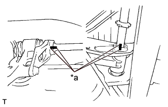
Text in Illustration *a Matchmark Align the matchmarks and install the rear end of torsion bar spring LH to the anchor arm sub-assembly LH.
-
Align the matchmark and install the tip of torsion bar spring LH to the front suspension torque arm LH.
-
Pass the adjusting hexagon bolt though the anchor arm sub-assembly LH through the anchor arm swivel LH and temporarily tighten with anchor arm adjust nut though anchor arm adjuster seat LH.
-
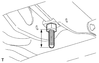
Tighten the anchor arm adjust nut so that the protrusion width of anchor arm adjusting hexagon bolt will be the dimension A when it was removed.
-
-
-
INSTALL ENGINE SIDE COVER SUB-ASSEMBLY LH
-
Single cab:
Install the 4 bolts and engine side cover LH.
- Torque:
- 11.5 N*m { 117 kgf*cm, 8 ft.*lbf }
-
Except Single cab:
Install the 3 bolts and engine side cover LH.
- Torque:
- 11.5 N*m { 117 kgf*cm, 8 ft.*lbf }
-
-
INSTALL FRONT WHEEL
- Torque:
- Full just low
- 365 N*m { 3722 kgf*cm, 269 ft.*lbf }
- Except full just low
- 135 N*m { 1377 kgf*cm, 100 ft.*lbf }
-
ADJUST FRONT WHEEL ALIGNMENT
-
FULLY TIGHTEN TORSION BAR SPRING
-
Fix anchor arm adjust nut, fully tighten the anchor arm lock nut.
- Torque:
- 78 N*m { 795 kgf*cm, 58 ft.*lbf }
-