TORSION BAR SPRING INSTALLATION

-
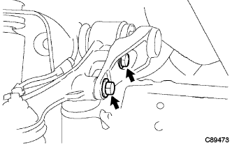
INSTALL FRONT SUSPENSION TORQUE ARM
-
Install the front suspension torque arm to the front upper suspension arm with the 2 bolts.
- Torque:
- 120 N*m { 1224 kgf*cm, 89 ft.*lbf }
-
-
TEMPORARILY TIGHTEN TORSION BAR SPRING
-
New torsion bar spring:
-
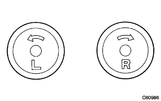
Identify left and right marks on the rear end of the torsion bar spring.
Note
The mark is at the rear end of the torsion bar spring.
-
Install the torsion bar dust cover to the torsion bar spring.
-
Apply MP grease to the spline at the both ends of the torsion bar spring.
-
Install the anchor arm to the frame.
-
Install the rear end of torsion bar spring to the anchor arm.
-
Install the tip of torsion bar spring to the front suspension torque arm.
-
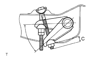
Pass the adjusting hexagon bolt through the anchor arm swivel, anchor arm, anchor arm adjuster seat, and temporarily tighten them with the anchor arm adjust nut.
Note
Install the anchor arm so that dimension C will be almost the same as dimension B when it was removed.
-
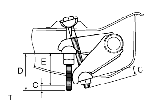
Tighten the adjust nut so that dimension E in the figure is the same as the reference value.
Dimension E Vehicle Model Dimension E KDY221R-TBMDYW 43 mm (1.693 in.) KDY221R-TBMDYW3 43 mm (1.693 in.) KDY221R-TLMGY 43 mm (1.693 in.) KDY221L-TBMDYW 43 mm (1.693 in.) KDY221L-TBMDYW3 43 mm (1.693 in.) KDY231R-TBMGYW3 49 mm (1.929 in.) KDY231R-TLMKY 49 mm (1.929 in.) KDY231L-TBMGYW3 49 mm (1.929 in.) KDY231L-PBMEYW3 41 mm (1.614 in.) KDY231L-PSMBYW 57 mm (2.244 in.) KDY231L-PSMBYW3 57 mm (2.244 in.) KDY251R-TBMGYW3 55 mm (2.165 in.) KDY251L-TBMGYW3 53 mm (2.087 in.) KDY251L-PBMEYW3 55 mm (2.165 in.) KDY261L-TBMGYW3 58 mm (2.283 in.) KDY261L-PBMEYW3 61 mm (2.402 in.) LY230R-TBMGSN3 50 mm (1.969 in.) Tech Tips
Dimension E = D - C
-
-
Reused torsion bar spring:
-
Identify left and right marks on the rear end of the torsion bar spring.
Note
The mark is at the rear end of the torsion bar spring.
-
Install the torsion bar dust cover to the torsion bar spring.
-
Apply MP grease to the spline at the both ends of torsion bar spring.
-
Install the anchor arm to the frame.
-
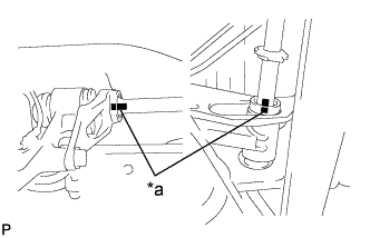
Text in Illustration *a Matchmark Align the matchmarks and install the rear end of torsion bar spring to the anchor arm.
-
Align the matchmarks and install the tip of torsion bar spring to the front suspension torque arm.
-
Pass the adjusting hexagon bolt through the anchor arm swivel, anchor arm, anchor arm adjuster seat, and temporarily tighten them with the anchor arm adjust nut.
-
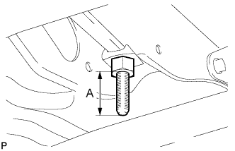
Tighten the anchor arm adjust nut so that dimension A of the hexagon bolt is the same as when it was removed.
-
-
-
INSTALL ENGINE SIDE COVER SUB-ASSEMBLY
-
Install the engine side cover with the 4 bolts (for Single Cab).
- Torque:
- 12 N*m { 117 kgf*cm, 8 ft.*lbf }
-
Install the engine side cover with the 3 bolts (for Double Cab).
- Torque:
- 12 N*m { 117 kgf*cm, 8 ft.*lbf }
-
-
INSTALL FRONT WHEEL
- Torque:
- for Full Just Low
- 365 N*m { 3722 kgf*cm, 270 ft.*lbf }
- for except Full Just Low
- 135 N*m { 1377 kgf*cm, 100 ft.*lbf }
-
INSPECT AND ADJUST FRONT WHEEL ALIGNMENT
-
FULLY TIGHTEN TORSION BAR SPRING
-
Fix the anchor arm adjust nut and fully tighten the anchor arm lock nut.
- Torque:
- 78 N*m { 795 kgf*cm, 58 ft.*lbf }
-