FRONT WHEEL ALIGNMENT (for Independent Type) ADJUSTMENT

-
INSPECT TIRES
-
Check the tires for wear and proper inflation pressure.
Cold tire inflation pressure for Rear Single Tire Model Tire Size Pressure Front Rear Front
kPa (kgf/cm2, psi)
Rear
kPa (kgf/cm2, psi)
KDY221R-TBMDYW 195/70R15C 104/102S 195/70R15C 104/102S 450 (4.5, 65) 450 (4.5, 65) KDY221R-TBMDYW3 KDY221L-TBMDYW KDY221L-TBMDYW3 KDY231L-PSMBYW KDY231L-PSMBYW3 LY225R-TBMDS 6.00R15-8PR 7.00R15-8PR 450 (4.5, 65) 400 (4.0, 58) LY225R-TBMDS3 LY225L-TBMDS LY225L-TBMDS3 LY235R-TBMFS 6.00R15-8PR 7.00R15-10PR 450 (4.5, 65) 525 (5.25, 76) LY235R-TBMFS3 LY235L-TBMFS LY235L-TBMFS3 for Rear Double Tire Model Tire Size Pressure Front Rear Front
kPa (kgf/cm2, psi)
Rear
kPa (kgf/cm2, psi)
KDY221R-TLMGY 195/75R15 109/107L 155R12-8PR 450 (4.5, 65) 450 (4.5, 65) KDY231R-TLMKY KDY231R-TBMGYW3 195/70R15C 104/102S 195/70R15C 104/102S 450 (4.5, 65) 350 (3.5, 51) KDY231L-TBMGYW3 KDY231L-PBMEYW3 KDY251R-TBMGYW3 KDY251L-TBMGYW3 KDY251L-PBMEYW3 KDY261L-TBMGYW3 KDY261L-PBMEYW3 LY230R-TBMGSN3 -
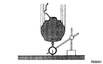
Using a dial indicator, check the tire runout.
Tire runout 3.0 mm (0.118 in.) or less
-
-
MEASURE VEHICLE HEIGHT
-
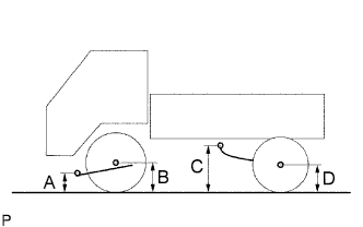
Bounce the vehicle up and down at the corners to stabilize the suspension and measure the vehicle height.
Vehicle height Vehicle Model B-A C-D KDY221R-TBMDYW 75 mm (2.95 in.) 83 mm (3.27 in.) KDY221R-TBMDYW3 75 mm (2.95 in.) 83 mm (3.27 in.) KDY221R-TLMGY 55 mm (2.17 in.) 99 mm (3.90 in.) KDY221L-TBMDYW 75 mm (2.95 in.) 83 mm (3.27 in.) KDY221L-TBMDYW3 75 mm (2.95 in.) 83 mm (3.27 in.) KDY231R-TBMGYW3 70 mm (2.76 in.) 104 mm (4.09 in.) KDY231R-TLMKY 52 mm (2.05 in.) 101 mm (3.98 in.) KDY231L-TBMGYW3 70 mm (2.76 in.) 104 mm (4.09 in.) KDY231L-PBMEYW3 82 mm (3.23 in.) 99 mm (3.90 in.) KDY231L-PSMBYW 73 mm (2.87 in.) 83 mm (3.27 in.) KDY231L-PSMBYW3 73 mm (2.87 in.) 83 mm (3.27 in.) KDY251R-TBMGYW3 71 mm (2.80 in.) 97 mm (3.82 in.) KDY251L-TBMGYW3 71 mm (2.80 in.) 97 mm (3.82 in.) KDY251L-PBMEYW3 72 mm (2.83 in.) 96 mm (3.78 in.) KDY261L-TBMGYW3 62 mm (2.44 in.) 99 mm (3.90 in.) KDY261L-PBMEYW3 60 mm (2.36 in.) 98 mm (3.86 in.) LY230R-TBMGSN3 63 mm (2.48 in.) 105 mm (4.13 in.) Measuring points A Ground clearance of lower arm front side cam bolt front and center B Ground clearance of front axle center C Ground clearance of rear leaf spring front side (No. 3 hanger) bolt center D Ground clearance of rear axle center Note
Before inspecting the wheel alignment, check the vehicle height.
-
-
INSPECT TOE-IN
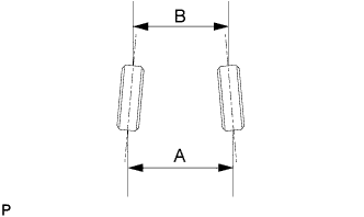
Toe-in (A-B) 4.0 +/- 2.0 mm (0.16 +/- 0.08 in.) If the toe-in is not within the specified range, adjust it at the rack ends.
-
ADJUST TOE-IN
-
Remove the rack boot set clips.
-
Loosen the tie rod end lock nuts.
-
Turn the right and left rack ends uniformly to adjust the toe-in.
Toe-in (A-B) 4.0 +/- 1.0 mm (0.16 +/- 0.04 in.) Tech Tips
Try to adjust the toe-in to the middle of the specified range.
-
Make sure that the lengths of the right and left rack ends are approximately the same.
Standard difference 0 +/- 1.0 mm (0 +/- 0.04 in.) -
Torque the tie rod end lock nuts.
- Torque:
- 91 N*m { 928 kgf*cm, 67 ft.*lbf }
-
Place the boots on the seats and install the clips.
Tech Tips
Make sure that the boots are not twisted.
-
-
INSPECT WHEEL TURNING ANGLE
-
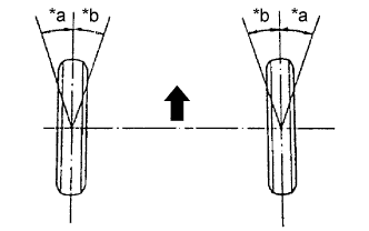
Text in Illustration *a Inside *b Outside 
Front Turn the steering wheel fully, and measure the wheel turning angle.
Wheel turning angle Inside wheel Outside wheel
(Reference)
38° (36° to 39°) 36° If the right and left inside wheel turning angles differ from the specified range, check the right and left rack end lengths.
-
-
INSPECT CAMBER, CASTER AND STEERING AXIS INCLINATION
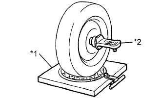
Text in Illustration *1 Alignment tester *2 Gauge
-
Install the camber-caster-kingpin gauge and position the front wheel on the wheel alignment tester.
-
Inspect the camber, caster and steering axis inclination.
Camber, caster and steering axis inclination Vehicle Model Camber Caster Steering Axis Inclination
(Reference)
KDY221R-TBMDYW 0°30' +/- 45'
(0.50° +/- 0.75°)
2°30' +/- 45'
(2.50° +/- 0.75°)
12°05'
(12.08°)
KDY221R-TBMDYW3 0°30' +/- 45'
(0.50° +/- 0.75°)
2°30' +/- 45'
(2.50° +/- 0.75°)
12°05'
(12.08°)
KDY221R-TLMGY 0°30' +/- 45'
(0.50° +/- 0.75°)
3°10' +/- 45'
(3.17° +/- 0.75°)
12°05'
(12.08°)
KDY221L-TBMDYW 0°30' +/- 45'
(0.50° +/- 0.75°)
2°30' +/- 45'
(2.50° +/- 0.75°)
12°05'
(12.08°)
KDY221L-TBMDYW3 0°30' +/- 45'
(0.50° +/- 0.75°)
2°30' +/- 45'
(2.50° +/- 0.75°)
12°05'
(12.08°)
KDY231R-TBMGYW3 0°30' +/- 45'
(0.50° +/- 0.75°)
2°00' +/- 45'
(2.00° +/- 0.75°)
12°05'
(12.08°)
KDY231R-TLMKY 0°30' +/- 45'
(0.50° +/- 0.75°)
3°10' +/- 45'
(3.17° +/- 0.75°)
12°05'
(12.08°)
KDY231L-TBMGYW3 0°30' +/- 45'
(0.50° +/- 0.75°)
2°00' +/- 45'
(2.00° +/- 0.75°)
12°05'
(12.08°)
KDY231L-PBMEYW3 0°30' +/- 45'
(0.50° +/- 0.75°)
2°00' +/- 45'
(2.00° +/- 0.75°)
12°05'
(12.08°)
KDY231L-PSMBYW 0°30' +/- 45'
(0.50° +/- 0.75°)
2°40' +/- 45'
(2.67° +/- 0.75°)
12°05'
(12.08°)
KDY231L-PSMBYW3 0°30' +/- 45'
(0.50° +/- 0.75°)
2°40' +/- 45'
(2.67° +/- 0.75°)
12°05'
(12.08°)
KDY251R-TBMGYW3 0°30' +/- 45'
(0.50° +/- 0.75°)
2°40' +/- 45'
(2.67° +/- 0.75°)
12°05'
(12.08°)
KDY251L-TBMGYW3 0°30' +/- 45'
(0.50° +/- 0.75°)
2°40' +/- 45'
(2.67° +/- 0.75°)
12°05'
(12.08°)
KDY251L-PBMEYW3 0°30' +/- 45'
(0.50° +/- 0.75°)
2°40' +/- 45'
(2.67° +/- 0.75°)
12°15'
(12.08°)
KDY261L-TBMGYW3 0°30' +/- 45'
(0.50° +/- 0.75°)
2°40' +/- 45'
(2.67° +/- 0.75°)
12°05'
(12.08°)
KDY261L-PBMEYW3 0°30' +/- 45'
(0.50° +/- 0.75°)
2°40' +/- 45'
(2.67° +/- 0.75°)
12°05'
(12.08°)
LY230R-TBMGSN3 0°30' +/- 45'
(0.50° +/- 0.75°)
2°20' +/- 45'
(2.33° +/- 0.75°)
12°05'
(12.08°)
Note
The tolerance for the difference between the left and right wheels is 30' (0.50°) or less for both the camber and caster.
If the camber and caster are not as specified, adjust them.
If the steering axis inclination is not as specified after the camber and caster have been correctly adjusted, recheck the steering knuckle and front wheel for distortion and slack.
-
-
ADJUST CAMBER AND CASTER
Note
Inspect the toe-in after the camber and caster have been adjusted.
-
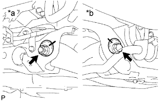
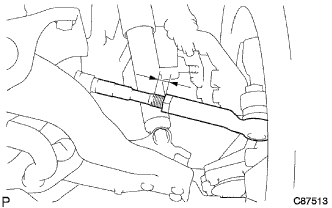
Text in Illustration *a Front Side *b Rear Side Loosen the nut and bolt.
-
Adjust the camber and the caster by turning the camber adjust cam and the No. 2 toe adjust plate.
Tech Tips
Try to adjust the camber and caster to the central values.
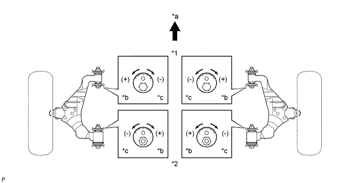
Text in Illustration *1 Camber Adjust Cam *2 No. 2 Toe Adjust Cam *a Front *b Longer *c Shorter - - Camber and caster Vehicle Model Camber Caster KDY221R-TBMDYW 0°30' +/- 30'
(0.50° +/- 0.50°)
2°30' +/- 30'
(2.50° +/- 0.50°)
KDY221R-TBMDYW3 0°30' +/- 30'
(0.50° +/- 0.50°)
2°30' +/- 30'
(2.50° +/- 0.50°)
KDY221R-TLMGY 0°30' +/- 30'
(0.50° +/- 0.50°)
3°10' +/- 45'
(3.17° +/- 0.75°)
KDY221L-TBMDYW 0°30' +/- 30'
(0.50° +/- 0.50°)
2°30' +/- 30'
(2.50° +/- 0.50°)
KDY221L-TBMDYW3 0°30' +/- 30'
(0.50° +/- 0.50°)
2°30' +/- 30'
(2.50° +/- 0.50°)
KDY231R-TBMGYW3 0°30' +/- 30'
(0.50° +/- 0.50°)
2°00' +/- 30'
(2.00° +/- 0.50°)
KDY231R-TLMKY 0°30' +/- 30'
(0.50° +/- 0.50°)
3°10' +/- 45'
(3.17° +/- 0.75°)
KDY231L-TBMGYW3 0°30' +/- 30'
(0.50° +/- 0.50°)
2°00' +/- 30'
(2.00° +/- 0.50°)
KDY231L-PBMEYW3 0°30' +/- 30'
(0.50° +/- 0.50°)
2°00' +/- 30'
(2.00° +/- 0.50°)
KDY231L-PSMBYW 0°30' +/- 30'
(0.50° +/- 0.50°)
2°40' +/- 30'
(2.67° +/- 0.50°)
KDY231L-PSMBYW3 0°30' +/- 30'
(0.50° +/- 0.50°)
2°40' +/- 30'
(2.67° +/- 0.50°)
KDY251R-TBMGYW3 0°30' +/- 30'
(0.50° +/- 0.50°)
2°40' +/- 30'
(2.67° +/- 0.50°)
KDY251L-TBMGYW3 0°30' +/- 30'
(0.50° +/- 0.50°)
2°40' +/- 30'
(2.67° +/- 0.50°)
KDY251L-PBMEYW3 0°30' +/- 30'
(0.50° +/- 0.50°)
2°40' +/- 30'
(2.67° +/- 0.50°)
KDY261L-TBMGYW3 0°30' +/- 30'
(0.50° +/- 0.50°)
2°40' +/- 30'
(2.67° +/- 0.50°)
KDY261L-PBMEYW3 0°30' +/- 30'
(0.50° +/- 0.50°)
2°40' +/- 30'
(2.67° +/- 0.50°)
LY230R-TBMGSN3 0°30' +/- 30'
(0.50° +/- 0.50°)
2°20' +/- 30'
(2.33° +/- 0.50°)
Note
The tolerance for the difference between the left and right wheels is 30' (0.50°) or less for both the camber and caster.
-
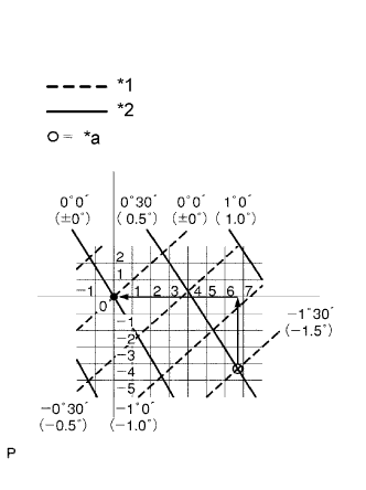
Text in Illustration *1 Caster *2 Camber *a Calculated Value How to read the adjustment chart (using examples).
-
Measure the present alignment.
Camber 1°00' (1.00°) Caster 1°00' (1.00°) -
Calculate the difference between the standard value (A) and the measured value (B) on the adjustment chart.
Standard value Camber 0°30' (0.50°) Caster 2°30' (2.50°) Formula B - A = C Camber 1°00' - (0°30') = 0°30' Caster 1°00' - (2°30') = -1°30' -
As shown in the chart, read the distance from the marked point to 0 point, and adjust the front and/or rear adjusting cams accordingly.
Camber adjust cam + (Longer) 4.5 No. 2 toe adjust plate - (Shorter) 6.7 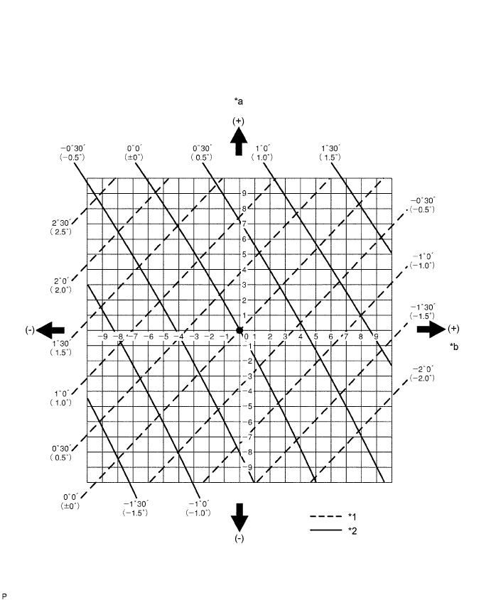
Text in Illustration *1 Caster *2 Camber *a Camber Adjust Cam *b No. 2 Toe Adjust Cam
-
-
Text in Illustration *a Front Side *b Rear Side Fully tighten the nut and bolt.
- Torque:
- 170 N*m { 1733 kgf*cm, 126 ft.*lbf }
-