STEERING KNUCKLE (for Independent Type) INSTALLATION

Tech Tips
Replace the RH side by the same procedures with the LH side.
-
INSTALL STEERING KNUCKLE LH
-
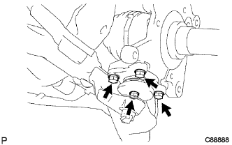
Install the steering knuckle LH to the lower ball joint with the 4 bolts.
- Torque:
- 57 N*m { 581 kgf*cm, 42 ft.*lbf }
-
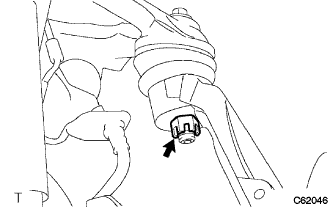
Install the stud of the upper ball joint to the steering knuckle and tighten with the castle nut.
- Torque:
- 140 N*m { 1428 kgf*cm, 103 ft.*lbf }
-
Install a new cotter pin.
Note
Perform hole matching for the cotter pin after tightening of the castle nut within 60° in the direction for further tightening.
-
-
INSTALL STEERING KNUCKLE ARM LH
-
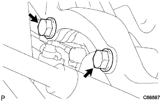
Apply sealant to the threads of 2 bolts.
-
Install the steering knuckle arm LH with the 2 bolts.
- Torque:
- 160 N*m { 1632 kgf*cm, 118 ft.*lbf }
Adhesive Toyota Genuine Adhesive 1344, Three Bond 1344 or equivalent
-
-
INSTALL SPEED SENSOR FRONT LH (W/ ABS)
-
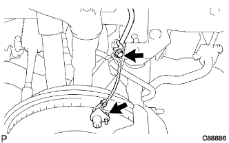
Install the speed sensor FR LH with the 2 bolts.
- Torque:
- 8.0 N*m { 82 kgf*cm, 71 in.*lbf }
-
-
INSTALL DISC BRAKE DUST COVER FRONT LH
-
Install the front brake dust cover LH with the 3 bolts.
- Torque:
- 19 N*m { 194 kgf*cm, 14 ft.*lbf }
-
-
INSTALL AXLE HUB W/DISC
-
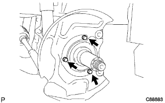
Clean the spindle part of the steering knuckle and apply a thin coating MP grease.
-
Install the front axle hub with brake disc on the steering knuckle.
Note
Do not damage the oil seal.
-
Install the front axle outer bearing roller bearing and front axle hub claw washer LH.
-
-
INSTALL FRONT WHEEL ADJUSTING NUT LH
-
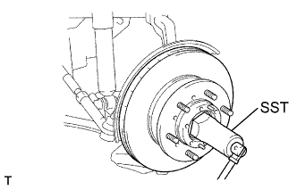
Using SST, tighten the bearing lock nut while turning the axle hub.
- SST
- 09607-60020
- Torque:
- 59 N*m { 600 kgf*cm, 44 ft.*lbf }
-
-
ADJUST PRELOAD
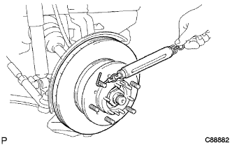
-
Move the front axle hub 2 or 3 times over the full range to let the bearing settle down.
-
Loosen the lock nut so far that it can be turned with the fingers (about 60°).
-
Using SST, tighten the bearing lock nut.
- SST
- 09607-60020
- Torque:
- 24 N*m { 245 kgf*cm, 18 ft.*lbf }
-
Using SST, install a new adjusting lock washer LH and adjusting nut LH.
- SST
- 09607-60020
- Torque:
- 47 N*m { 480 kgf*cm, 35 ft.*lbf }
-
Using spring tension gauge, measure the range of the reference value for the staring torque.
Preload (at starting) Rear single tire 18.6 to 47.2 N (1.90 to 4.81 kgf, 4.18 to 10.61 lbf) Rear double tire 14.1 to 35.8 N (1.44 to 3.65 kgf, 3.17 to 8.05 lbf) Note
When the reference value is off, vary the amount by which the lock nut is returned and adjust again.
-
Confirm smooth rotation of the front axle hub.
-
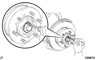
Secure the adjusting nut and lock nut by bending one of the lock washer teeth inward and the other lock washer teeth outward.
-
-
INSTALL FRONT AXLE HUB GREASE CAP LH
-
Install a new outer shaft flange gasket LH and hub grease cap LH with the 6 bolts.
- Torque:
- 11.5 N*m { 117 kgf*cm, 8 ft.*lbf }
-
-
INSTALL FRONT DISC BRAKE CALIPER ASSEMBLY LH
- Torque:
- 147 N*m { 1500 kgf*cm, 108 ft.*lbf }
-
INSTALL FRONT WHEEL
- Torque:
- Rear single tire
- 135 N*m { 1377 kgf*cm, 100 ft.*lbf }
- Rear double tire
- 365 N*m { 3722 kgf*cm, 269 ft.*lbf }
-
CHECK ABS SPEED SENSOR SIGNAL (w/ ABS)