DIFFERENTIAL CARRIER ASSEMBLY (for Ring Gear Size 10.5 inch) REASSEMBLY

-
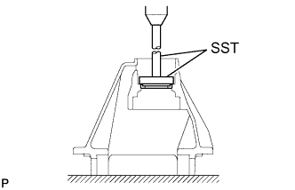
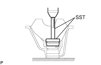
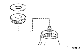
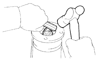
INSTALL REAR DIFFERENTIAL DUST DEFLECTOR (for 2 Pinion Gear Type)
-
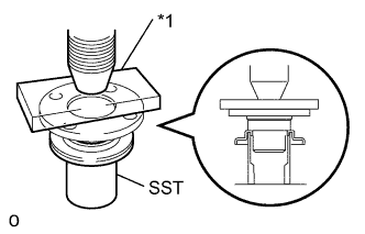
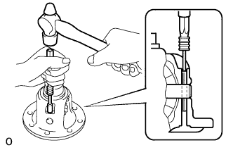
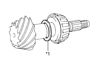
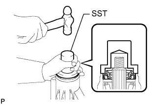
Text in Illustration *1 Steel Plate Using SST, a press and steel plate, press in a new dust deflector.
- SST
- 09523-36010
Note
Be careful not to damage the dust deflector.
-
-
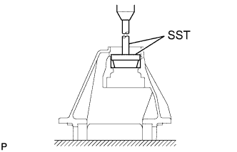
INSTALL REAR DIFFERENTIAL DUST DEFLECTOR (for 4 Pinion Gear Type)
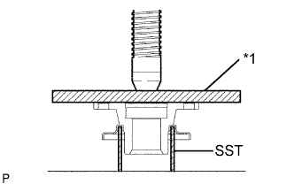
Text in Illustration *1 Steel Plate
-
Using SST, a press and steel plate, press in a new dust deflector.
- SST
- 09631-12090
Note
Be careful not to damage the dust deflector.
-
-
INSTALL DIFFERENTIAL CASE (for 2 Pinion Gear Type)
-
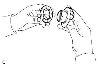
Install the 2 side gear thrust washers to the side gears.
-
Install the 2 side gears with the thrust washers, 2 pinion gears, 2 pinion gear thrust washers and the pinion shaft.
Tech Tips
-
Align the straight pin holes of the differential case and the pinion shaft.
-
Apply hypoid gear oil to each sliding surface and rotating part.
-
-
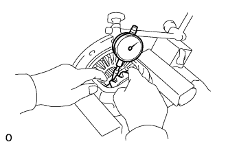
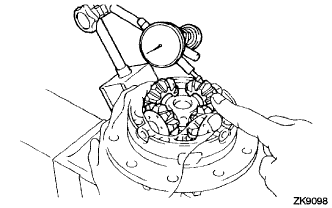
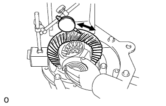
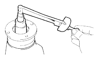
Using a dial indicator, measure the side gear backlash while holding one pinion gear toward the differential case.
Standard backlash 0.15 mm (0.00591 in.) or less If the backlash is not within the specification, replace the side gear thrust washer with one of an appropriate thickness.
Tech Tips
Refer to the following table to select thrust washers which will ensure that the backlash is within the specification.
Thrust Washer Thickness Thickness mm (in.) Thickness mm (in.) 1.53 to 1.57 (0.0602 to 0.0618) 1.78 to 1.82 (0.0701 to 0.0171) 1.58 to 1.62 (0.0622 to 0.0638) 1.83 to 1.87 (0.0720 to 0.0736) 1.63 to 1.67 (0.0642 to 0.0657) 1.88 to 1.92 (0.0740 to 0.0756) 1.68 to 1.72 (0.0661 to 0.0677) 1.93 to 1.97 (0.0760 to 0.0776) 1.73 to 1.77 (0.0681 to 0.0697) - -
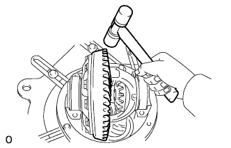
Using a pin punch 5 mm and hammer, tap the straight pin through the holes in the differential case and the pinion shaft.
-
Using a chisel and hammer, stake the outside of the differential case pin hole.
-
-
INSTALL DIFFERENTIAL CASE (for 4 Pinion Gear Type)
-
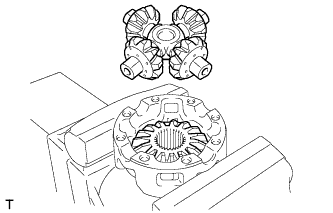
Install the rear differential side gear thrust washer to the rear differential side gear.
-
Install the rear differential pinion thrust washer and the rear differential pinion to the rear differential spider.
Tech Tips
Apply hypoid gear oil to each sliding surface and rotating part.
-
Secure the differential case in a vise using aluminum plates.
Note
Do not overtighten the vise, as the differential case may become deformed.
-
Install the rear differential side gear and the rear differential spider to the differential case RH.
-
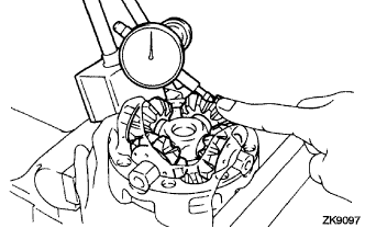
Using a dial indicator, measure the differential case RH side backlash while holding the pinion toward the case.
Standard backlash 0.02 to 0.20 mm (0.000788 to 0.00787 in.) -
Remove the rear differential spider from the differential case RH.
-
Install the rear differential side gear and the rear differential spider to the differential case LH.
-
Using a dial indicator, measure the differential case LH side backlash while holding the pinion toward the case.
Standard backlash 0.02 to 0.20 mm (0.000788 to 0.00787 in.) If the backlash is not within the specification, install the 2 side gear thrust washers with different thickness.
Tech Tips
Refer to the following table to select thrust washers which will ensure that the backlash is within the specification.
Thrust Washer Thickness Thickness mm (in.) Thickness mm (in.) 1.53 to 1.57 (0.0602 to 0.0618) 1.83 to 1.87 (0.0720 to 0.0736) 1.58 to 1.62 (0.0622 to 0.0638) 1.88 to 1.92 (0.0740 to 0.0756) 1.63 to 1.67 (0.0641 to 0.0657) 1.93 to 1.97 (0.0760 to 0.0776) 1.68 to 1.72 (0.0661 to 0.0677) 1.98 to 2.02 (0.0780 to 0.0795) 1.73 to 1.77 (0.0681 to 0.0697) 2.03 to 2.07(0.0800 to 0.0815) 1.78 to 1.82 (0.0700 to 0.0717) 2.08 to 2.12 (0.0819 to 0.0835) -
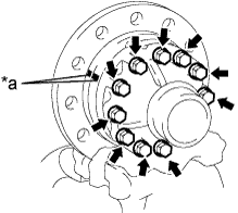
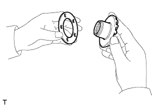
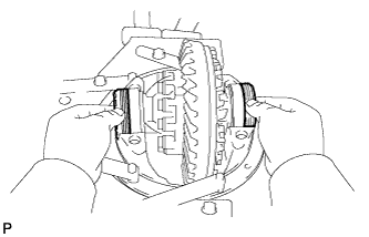
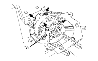
Text in Illustration *a Matchmark Align the matchmarks and assemble the RH and LH cases.
-
Using a plastic hammer, install the differential case.
-
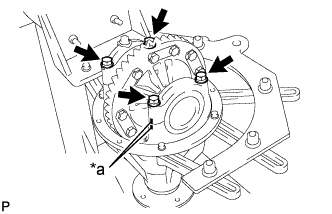
Install the 12 bolts.
- Torque:
- 79 N*m { 800 kgf*cm, 58 ft.*lbf }
-
-
INSTALL REAR DIFFERENTIAL CASE BEARING (for 2 Pinion Gear Type)
-
Using SST and a press, press in the 2 rear differential case bearings.
- SST
- 09950-60010 ( 09951-00500, 09951-00630 )
- 09950-70010 ( 09951-07150 )
-
-
INSTALL REAR DIFFERENTIAL CASE BEARING (for 4 Pinion Gear Type)
-
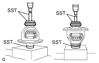
Using SST and a press, install the 2 rear differential case bearings on the differential case.
- SST
- 09316-20011
- 09950-60010 ( 09951-00500 )
-
-
INSTALL DIFFERENTIAL RING GEAR (for 2 Pinion Gear Type)
Text in Illustration *a Boiling Water
-
Clean the contact surfaces of the differential case and the ring gear.
-
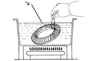
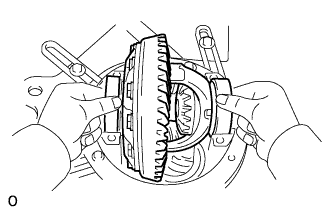
Heat the ring gear to approximately 100°C (212°F) in boiling water.
-
Carefully take the ring gear out of the boiling water.
-
Text in Illustration *a Adhesive *b Matchmark After the moisture on the ring gear has completely evaporated, quickly set the ring gear onto the differential case.
Tech Tips
Align the matchmarks on the ring gear and differential case.
-
After the ring gear cools down sufficiently, apply adhesive to the 12 bolts and install them.
Adhesive Toyota Genuine Adhesive 1360K, Three Bond 1360K or equivalent - Torque:
- 197 N*m { 2008 kgf*cm, 145 ft.*lbf }
-
-
INSTALL DIFFERENTIAL RING GEAR (for 4 Pinion Gear Type)
-
Clean the contact surfaces of the differential case and the ring gear.
-
Heat the ring gear to approximately 100°C (212°F) in boiling water.
Text in Illustration *a Boiling Water -
Carefully take the ring gear out of the boiling water.
-
After the moisture on the ring gear has completely evaporated, quickly install the ring gear to the differential case.
-
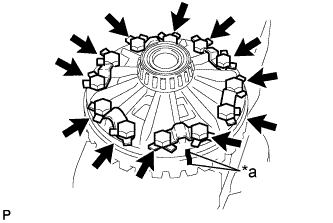
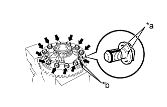
Text in Illustration *a Matchmark Align the matchmarks on the ring gear and differential case.
-
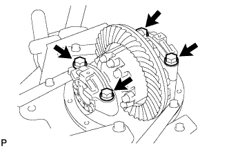
Temporarily install 6 new lock plates and 12 bolts.
-
After the ring gear cools down enough, tighten the 12 bolts uniformly at a time.
- Torque:
- 162 N*m { 1650 kgf*cm, 119 ft.*lbf }
-
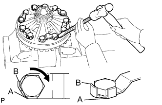
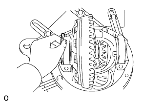
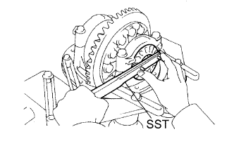
Using a chisel and a hammer, stake the 6 lock plates.
Tech Tips
-
Stake one claw so that it is flush with the flat surface of the bolt.(A)
-
For the claw contacting the protruding portion of the bolt, stake only the half on the tightening side.(B)
-
-
-
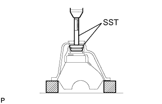
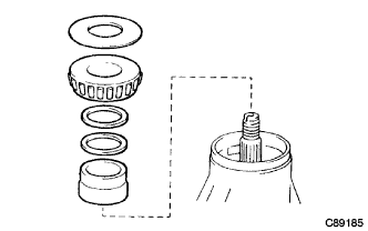
INSTALL DIFFERENTIAL OIL STORAGE RING
-
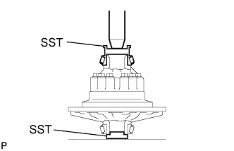
Using SST and a press, press in the oil storage ring to the differential carrier.
- SST
- 09950-70010 ( 09951-07150 )
- 09950-60020 ( 09951-00750 )
-
-
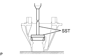
INSTALL REAR DRIVE PINION FRONT TAPERED ROLLER BEARING (for 2 Pinion Gear Type)
-
Using SST and a press, press in the rear drive pinion front tapered roller bearing outer race to the differential carrier.
- SST
- 09950-60020 ( 09951-00810 )
- 09950-70010 ( 09951-07150 )
-
-
INSTALL REAR DRIVE PINION FRONT TAPERED ROLLER BEARING (for 4 Pinion Gear Type)
-
Using SST and a press, install the rear drive pinion front tapered roller bearing outer race to the differential carrier.
- SST
- 09950-60020 ( 09951-00780 )
- 09950-70010 ( 09951-07150 )
-
-
INSTALL REAR DRIVE PINION REAR TAPERED ROLLER BEARING (for 2 Pinion Gear Type)
-
Using SST and a press, press in the rear drive pinion rear tapered roller bearing outer race to the differential carrier.
- SST
- 09950-60020 ( 09951-01030 )
- 09950-70010 ( 09951-07360 )
-
-
INSTALL REAR DRIVE PINION REAR TAPERED ROLLER BEARING (for 4 Pinion Gear Type)
-
Using SST and a press, install the rear drive pinion rear tapered roller bearing outer race to the differential carrier.
- SST
- 09950-60020 ( 09951-01030 )
- 09950-70010 ( 09951-07150 )
-
-
INSTALL REAR DRIVE PINION REAR TAPERED ROLLER BEARING (for 2 Pinion Gear Type)
-
Install the plate washer onto the drive pinion.
Tech Tips
First fit a washer with the same thickness as the removed washer, and then check the tooth contact pattern. Replace the washer with one of a different thickness if necessary.
-
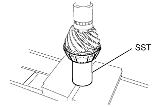
Using SST and a press, install the rear drive pinion rear tapered roller bearing (inner race) onto the drive pinion.
- SST
- 09630-24014 ( 09620-24051 )
-
-
INSTALL REAR DRIVE PINION REAR TAPERED ROLLER BEARING (for 4 Pinion Gear Type)
-
Install the removed plate washer on the drive pinion.
-
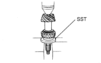
Using SST and a press, install the rear drive pinion rear tapered roller bearing (inner race) onto the drive pinion.
- SST
- 09506-35010
-
-
ADJUST DIFFERENTIAL DRIVE PINION PRELOAD (for 2 Pinion Gear Type)
-
Install the bearing spacer onto the drive pinion.
-
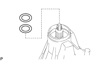
Install the 2 preload adjusting shims.
-
Install the front tapered roller bearing and the oil slinger.
Tech Tips
Install the oil seal after adjusting the gear contact pattern.
-
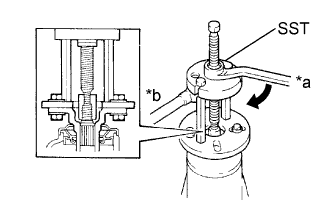
Text in Illustration *a Turn *b Hold Using SST, install the rear drive pinion companion flange sub-assembly.
- SST
- 09950-30012 ( 09951-03010, 09953-03010, 09954-03010, 09956-03040 )
-
Coat the threads of a new rear drive pinion nut with hypoid gear oil LSD.
-
Text in Illustration *a Turn *b Hold Using SST to hold the rear drive pinion companion flange sub-assembly, install the rear drive pinion nut by tightening it until the standard preload is reached.
- SST
- 09330-00021 ( 09330-00030 )
- Torque:
- 304 N*m { 3100 kgf*cm, 224 ft.*lbf }
Note
As there is no spacer, torque a little at a time, being careful not to overtighten it.
-
Using a torque wrench, measure the preload.
Standard Preload (at Starting) Bearing Specified Condition New 1.80 to 3.17 N*m (19 to 32 kgf*cm, 16 to 28 in.*lbf) Reused 1.62 to 2.25 N*m (17 to 22 kgf*cm, 15 to 19 in.*lbf) Tech Tips
Measure the total preload after first turning the bearing clockwise and counterclockwise several times to make the bearing smooth.
If the preload is not within the specification, adjust the preload until it is within the specification by performing the following procedures.
-
Refer to the table below and choose a combination of 2 shims.
Preload Adjusting Shim Shim A Thickness mm (in.) Shim B Thickness mm (in.) 1.89 to 1.91 (0.0745 to 0.0753) 1.792 to 1.808 (0.0706 to 0.0712) 1.99 to 2.01 (0.0784 to 0.0792) 1.802 to 1.818 (0.0710 to 0.0716) 2.09 to 2.11 (0.0823 to 0.0831) 1.812 to 1.828 (0.0714 to 0.0720) 2.19 to 2.21 (0.0863 to 0.0871) 1.822 to 1.838 (0.0718 to 0.0724) 2.29 to 2.31 (0.0902 to 0.0910) 1.832 to 1.848 (0.0722 to 0.0728) 2.39 to 2.41 (0.0942 to 0.0950) 1.842 to 1.858 (0.0726 to 0.0732) 2.49 to 2.51 (0.0981 to 0.0989) 1.852 to 1.868 (0.0730 to 0.0736) 2.59 to 2.61 (0.1020 to 0.1028) 1.862 to 1.878 (0.0734 to 0.0740) 2.69 to 2.71 (0.1060 to 0.1068) 1.872 to 1.888 (0.0738 to 0.0744) 2.79 to 2.81 (0.1099 to 0.1107) 1.882 to 1.898 (0.0742 to 0.0748) 2.89 to 2.91 (0.1139 to 0.1147) - 2.99 to 3.01 (0.1178 to 0.1186) - -
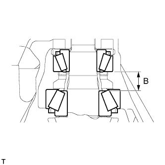
Calculate the B measurement.
B measurement Shim A + Shim B + Spacer = B measurement Spacer Measurement mm (in.) 24.15 to 24.20 (0.9515 to 0.9535) Preload Adjusting Shim Pairing Table (Reference) Shim A Thickness mm (in.) Shim B Thickness mm (in.) B Measurement mm (in.) 1.89 to 1.91 (0.0745 to 0.0753) 1.792 to 1.808 (0.0706 to 0.0712) 27.832 to 27.918 (1.0966 to 1.1000) ↑ 1.802 to 1.818 (0.0710 to 0.0716) 27.842 to 27.928 (1.0970 to 1.1004) ↑ 1.812 to 1.828 (0.0714 to 0.0720) 27.852 to 27.938 (1.0974 to 1.1008) ↑ 1.822 to 1.838 (0.0718 to 0.0724) 27.862 to 27.948 (1.0978 to 1.1012) ↑ 1.832 to 1.848 (0.0722 to 0.0728) 27.872 to 27.958 (1.0982 to 1.1015) ↑ 1.842 to 1.858 (0.0726 to 0.0732) 27.882 to 27.968 (1.0986 to 1.1019) ↑ 1.852 to 1.868 (0.0730 to 0.0736) 27.892 to 27.978 (1.0989 to 1.1023) ↑ 1.862 to 1.878 (0.0734 to 0.0740) 27.902 to 27.988 (1.0993 to 1.1027) ↑ 1.872 to 1.888 (0.0738 to 0.0744) 27.912 to 27.998 (1.0997 to 1.1031) ↑ 1.882 to 1.898 (0.0742 to 0.0748) 27.922 to 28.008 (1.1001 to 1.1035) 1.99 to 2.01 (0.0784 to 0.0792) 1.792 to 1.808 (0.0706 to 0.0712) 27.932 to 28.018 (1.1005 to 1.1039) ↑ 1.802 to 1.818 (0.0710 to 0.0716) 27.942 to 28.028 (1.1009 to 1.1043) ↑ 1.812 to 1.828 (0.0714 to 0.0720) 27.952 to 28.038 (1.1013 to 1.1047) For these in-between values, combine shim A, B and the spacer as above so that the B measurement changes at 0.01 mm (0.000394 in.) intervals. 27.962 to 28.048 (1.1017 to 1.1051)
to
29.012 to 29.098 (1.1431 to 1.1465)
2.99 to 3.01 (0.1178 to 0.1186) 1.882 to 1.898 (0.0742 to 0.0748) 29.022 to 29.108 (1.1435 to 1.1469) -
Measure the preload.
-
Change the shims so that the B measurement changes by 0.01 mm (0.000394 in.), and measure the preload.
Standard Preload (at Starting) Bearing Specified Condition New 1.80 to 3.17 N*m (19 to 32 kgf*cm, 16 to 28 in.*lbf) Reused 1.62 to 2.25 N*m (17 to 22 kgf*cm, 15 to 19 in.*lbf) Tech Tips
Repeat the above procedure until the preload is as specified.
-
-
ADJUST DIFFERENTIAL DRIVE PINION PRELOAD (for 4 Pinion Gear Type)
-
Install the drive pinion, spacer, 2 shims, front tapered roller bearing and the oil slinger.
Tech Tips
-
When replace the drive pinion bearing, install the thickest shim A and B.
-
Assemble and install the oil seal after adjusting the total preload.
-
-
Text in Illustration *a Turn *b Hold Using SST, install the rear drive pinion companion flange sub-assembly.
- SST
- 09950-30012 ( 09951-03010, 09953-03010, 09954-03010, 09955-03030, 09956-03040 )
-
Coat the threads of a new rear drive pinion nut with hypoid gear oil LSD.
-
Text in Illustration *a Turn *b Hold Using SST to hold the rear drive pinion companion flange sub-assembly, install the rear drive pinion nut by tightening it until the standard preload is reached.
- SST
- 09330-00021 ( 09330-00030 )
- Torque:
- 355 N*m { 3620 kgf*cm, 262 ft.*lbf }
Note
As there is no spacer, torque a little at a time, being careful not to overtighten it.
-
Using a dial indicator, measure and note the drive pinion axial play.
-
Calculate the value "T". T = 4.89 mm (0.1925 in.) - (drive pinion axal play) Select shims A and B so that the sum of the 2 shims is closest to value "T"
Shim A thickness mm (in.) at intervals of 0.1 (0.00394) Shim B thickness mm (in.) at intervals of 0.01 (0.000394) 1.90 (0.0748) to 2.50 (0.0984) 1.80 (0.0709) to 1.85 (0.0728) 2.00 (0.0787) to 2.60 (0.1024) 1.81 (0.0713) to 1.86 (0.0732) 2.10 (0.0827) to 2.70 (0.1063) 1.82 (0.0717) to 1.87 (0.0736) 2.20 (0.0866) to 2.80 (0.1102) 1.83 (0.0720) to 1.88 (0.0740) 2.30 (0.0906) to 2.90 (0.1142) 1.84 (0.0724) to 1.89 (0.0744) 2.40 (0.0945) to 3.00 (0.1181) - -
Using a torque wrench, measure the preload.
Standard Preload (at Starting) Bearing Specified Condition New 2.00 to 5.39 N*m (20 to 55 kgf*cm, 18 to 48 in.*lbf) Reused 1.00 to 2.76 N*m (10 to 28 kgf*cm, 8.9 to 24 in.*lbf)
-
-
INSTALL DIFFERENTIAL CASE ASSEMBLY (for 2 Pinion Gear Type)
-
Place the 2 case bearing outer races on their corresponding bearings.
Tech Tips
Make sure the right and left races are not interchanged.
-
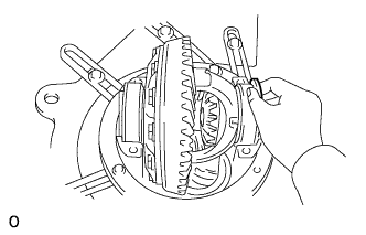
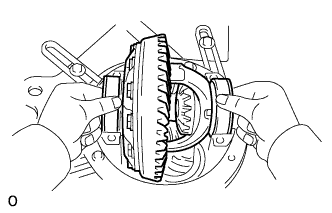
Install the differential case assembly in the differential carrier assembly.
-
-
INSTALL DIFFERENTIAL CASE ASSEMBLY (for 4 Pinion Gear Type)
-
Place the 2 case bearing outer races on their corresponding bearings.
Tech Tips
Make sure the right and left races are not interchanged.
-
Install the differential case assembly in the differential carrier assembly.
-
Install the 2 adjusting nuts on the differential carrier, making sure the adjusting nuts are threaded properly.
-
-
INSPECT AND ADJUST DIFFERENTIAL RING GEAR BACKLASH (for 2 Pinion Gear Type)
-
Install the plate washer on the ring gear back side.
Note
Make sure that the ring gear has backlash.
-
Tap on the ring gear with a plastic hammer so that the washer fits to the bearing.
-
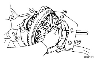
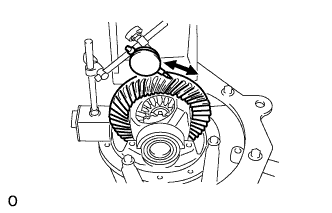
Using a dial indicator, while holding the rear drive pinion companion flange sub-assembly, measure the ring gear backlash.
Standard backlash (reference) 0.10 to 0.20 mm (0.00394 to 0.00787 in.) -
Select a ring gear back side plate washer using the backlash as a reference.
-
Select a ring gear teeth side plate washer so that there is no clearance between the case bearing outer race and the case.
-
Remove the 2 plate washers and the differential case.
-
Install the plate washer on the ring gear back side.
-
Place the other plate washer onto the differential case together with the case bearing outer race, and install the differential case with the case bearing outer race into the differential carrier.
-
Tap on the ring gear with a plastic-faced hammer so that the washers fit to the bearing.
-
Using a dial indicator, while holding the rear drive pinion companion flange sub-assembly, measure the ring gear backlash.
Standard backlash 0.10 to 0.20 mm (0.00394 to 0.00787 in.) If the backlash is not within the specification values, adjust it by either increasing or decreasing the thickness of washers on both sides by an equal amount.
Tech Tips
There should be no clearance between the plate washer and the case. Make sure that there is ring gear backlash.
-
-
ADJUST SIDE BEARING PRELOAD (for 2 Pinion Gear Type)
-
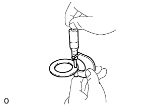
Remove the ring gear teeth side plate washer and using a micrometer, measure the thickness.
-
Install the selected plate washer.
-
Using the backlash as a reference, tap a new washer that is 0.05 to 0.20 mm (0.00197 to 0.00787 in.) thicker than the removed washer so that it fits to the bearing.
Tech Tips
Select a washer which can be pressed in 2/3 of the full amount with your finger.
-
Using a plastic-faced hammer, install the plate washer.
-
Recheck the ring gear backlash.
Standard backlash 0.10 to 0.20 mm (0.00394 to 0.00787 in.) If the backlash is not within the specification, adjust it by either increasing or decreasing the thickness of washers on both sides by an equal amount.
Tech Tips
The backlash will change by about 0.02 mm (0.000787 in.), corresponding to a 0.03 mm (0.00118 in.) change in the plate washer.
Washer Thickness Mark Thickness mm (in.) Mark Thickness mm (in.) 66 1.65 to 1.67 (0.0650 to 0.0658) 08 2.07 to 2.09 (0.0816 to 0.0823) 68 1.67 to 1.69 (0.0658 to 0.0666) 10 2.09 to 2.11 (0.0823 to 0.0831) 70 1.69 to 1.71 (0.0666 to 0.0674) 12 2.11 to 2.13 (0.0831 to 0.0839) 72 1.71 to 1.73 (0.0674 to 0.0682) 14 2.13 to 2.15 (0.0839 to 0.0847) 74 1.73 to 1.75 (0.0682 to 0.0690) 16 2.15 to 2.17 (0.0847 to 0.0855) 76 1.75 to 1.77 (0.0690 to 0.0697) 18 2.17 to 2.19 (0.0855 to 0.0863) 78 1.77 to 1.79 (0.0697 to 0.0705) 20 2.19 to 2.21 (0.0863 to 0.0871) 80 1.79 to 1.81 (0.0705 to 0.0713) 22 2.21 to 2.23 (0.0871 to 0.0879) 82 1.81 to 1.83 (0.0713 to 0.0721) 24 2.23 to 2.25 (0.0879 to 0.0887) 84 1.83 to 1.85 (0.0721 to 0.0729) 26 2.25 to 2.27 (0.0887 to 0.0894) 86 1.85 to 1.87 (0.0729 to 0.0737) 28 2.27 to 2.29 (0.0894 to 0.0902) 88 1.87 to 1.89 (0.0737 to 0.0745) 30 2.29 to 2.31 (0.0902 to 0.0891) 90 1.89 to 1.91 (0.0745 to 0.0753) 32 2.31 to 2.33 (0.0910 to 0.0918) 92 1.91 to 1.93 (0.0753 to 0.0760) 34 2.33 to 2.35 (0.0918 to 0.0926) 94 1.93 to 1.95 (0.0760 to 0.0768) 36 2.35 to 2.37 (0.0926 to 0.0934) 96 1.95 to 1.97 (0.0768 to 0.0776) 38 2.37 to 2.39 (0.0934 to 0.0942) 98 1.97 to 1.99 (0.0776 to 0.0784) 40 2.39 to 2.41 (0.0942 to 0.0950) 00 1.99 to 2.01 (0.0784 to 0.0792) 42 2.41 to 2.43 (0.0950 to 0.0957) 02 2.01 to 2.03 (0.0792 to 0.0800) 44 2.43 to 2.45 (0.0957 to 0.0965) 04 2.03 to 2.05 (0.0800 to 0.0808) 46 2.45 to 2.47 (0.0965 to 0.0973) 06 2.05 to 2.07 (0.0808 to 0.0816) - -
-
-
INSTALL BEARING CAP (for 2 Pinion Gear Type)
-
Text in Illustration *a Matchmark Align the matchmarks on the cap and the differential carrier.
-
Install the 4 bolts.
- Torque:
- 205 N*m { 2090 kgf*cm, 151 ft.*lbf }
Tech Tips
After rotating the ring gear 5 times or more, recheck the backlash.
-
-
INSPECT AND ADJUST DIFFERENTIAL RING GEAR BACKLASH (for 4 Pinion Gear Type)
-
Align the matchmarks on the cap and the differential carrier.
Text in Illustration *a Matchmark -
Install the right and left bearing caps with the 4 bolts.
- Torque:
- 205 N*m { 2090 kgf*cm, 151 ft.*lbf }
Tech Tips
-
If the bearing cap does not fit tightly on the differential carrier, the adjusting nuts are not threaded properly.
-
Reinstall the adjusting nuts if necessary.
-
Tighten the 4 bearing cap bolts to the specified torque, then loosen them to the point where the adjusting nuts can be turned by SST.
- SST
- 09504-00011
-
Using the SST, tighten the adjusting nut on the ring gear side until the ring has a backlash of about 0.2 mm (0.00787 in.).
- SST
- 09504-00011
-
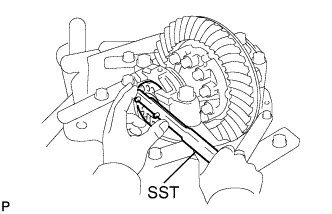
While turning the ring gear, use SST to fully tighten the adjusting nut on the drive pinion side. After the bearings as settled, loosen the adjusting nut on the drive pinion side.
- SST
- 09504-00011
-
Using SST, tighten the adjusting nut 1 to 1.5 notches from the 0 preload position.
-
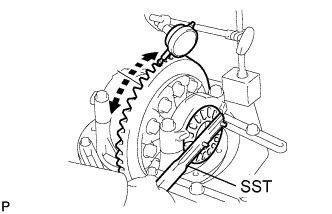
Using a dial indicator, adjust the ring gear backlash until it is within the specification.
Standard backlash 0.15 to 0.20 mm (0.00591 to 0.00787 in.) Tech Tips
-
The backlash is adjusted by turning the left and right adjusting nuts an equal amount. For example, loosen the adjusting nut on the right side one notch and loosen the adjusting nut on the left side one notch.
-
Perform the measurement at 3 or more positions around the circumference of the ring gear.
-
-
Tighten the bearing cap bolts.
- Torque:
- 205 N*m { 2090 kgf*cm, 151 ft.*lbf }
-
-
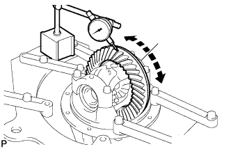
INSPECT DIFFERENTIAL RING GEAR RUNOUT
-
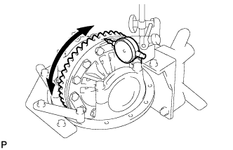
Using a dial indicator, measure the runout of the ring gear.
Maximum runout for 2 Pinion Gear Type 0.05 mm (0.00197 in.) for 4 Pinion Gear Type 0.01 mm (0.000393 in.) If the runout is greater than the maximum, replace the ring gear with a new one.
-
-
INSPECT TOTAL PRELOAD
-
Using a torque wrench, measure the preload with the teeth of the drive pinion and ring gear in contact.
Standard Total Preload (at Starting) Type Bearing Specified Condition for 2 Pinion Gear New Standard drive pinion preload + 0.22 to 0.41 N*m (3 to 4 kgf*cm, 2 to 3 in.*lbf) Reused Standard drive pinion preload + 0.19 to 0.38 N*m (2.0 to 3.8 kgf*cm, 1.7 to 3.4 in.*lbf) for 4 Pinion Gear New or Reused Standard drive pinion preload + 0.20 to 0.39 N*m (2.1 to 3.9 kgf*cm, 1.8 to 3.4 in.*lbf)
-
-
INSPECT TOOTH CONTACT BETWEEN RING GEAR AND DRIVE PINION
-
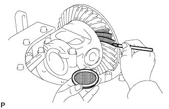
Coat 3 or 4 teeth at 3 different positions on the ring gear with Prussian blue.
-
Turn the rear drive pinion companion flange sub-assembly in both directions to inspect the ring gear for proper tooth contact.
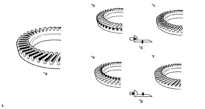
Text in Illustration *a Proper Contact *b Heel Contact *c Face Contact *d Select an adjusting washer that will bring the drive pinion closer to the ring gear. *e Toe Contact *f Flank Contact *g Select an adjusting washer that will shift the drive pinion away from the ring gear. - -
-
Text in Illustration *1 Plate Washer If the teeth are not contacting properly, use the following table to select a proper washer for correction.
Standard Plate Washer Thickness (for 2 Pinion Gear Type) Thickness mm (in.) Thickness mm (in.) 0.99 to 1.01 (0.0390 to 0.398) 1.265 to 1.285 (0.0498 to 0.0506) 1.015 to 1.035 (0.0399 to 0.0408) 1.29 to 1.31 (0.0508 to 0.0516) 1.04 to 1.06 (0.0410 to 0.0418) 1.315 to 1.335 (0.0518 to 0.0526) 1.065 to 1.085 (0.0409 to 0.0427) 1.34 to 1.36 (0.0528 to 0.0536) 1.09 to 1.11 (0.0420 to 0.0437) 1.365 to 1.385 (0.0538 to 0.0546) 1.115 to 1.135 (0.0429 to 0.0447) 1.39 to 1.41 (0.0548 to 0.0556) 1.14 to 1.16 (0.0439 to 0.0457) 1.415 to 1.435 (0.0558 to 0.0565) 1.165 to 1.185 (0.0449 to 0.0467) 1.44 to 1.46 (0.0567 to 0.0575) 1.19 to 1.21 (0.0469 to 0.0477) 1.465 to 1.485 (0.0577 to 0.0585) 1.215 to 1.235 (0.0479 to 0.0487) 1.49 to 1.51 (0.0587 to 0.0595) 1.24 to 1.26 (0.0489 to 0.0496) - Standard Plate Washer Thickness (for 4 Pinion Gear Type) Thickness mm (in.) Thickness mm (in.) 1.04 to 1.06 (0.0410 to 0.0418) 1.315 to 1.335 (0.0518 to 0.0526) 1.065 to 1.085 (0.0409 to 0.0427) 1.34 to 1.36 (0.0528 to 0.0536) 1.09 to 1.11 (0.0420 to 0.0437) 1.365 to 1.385 (0.0538 to 0.0546) 1.115 to 1.135 (0.0429 to 0.0447) 1.39 to 1.41 (0.0548 to 0.0556) 1.14 to 1.16 (0.0439 to 0.0457) 1.415 to 1.435 (0.0558 to 0.0565) 1.165 to 1.185 (0.0449 to 0.0467) 1.44 to 1.46 (0.0567 to 0.0575) 1.19 to 1.21 (0.0469 to 0.0477) 1.465 to 1.485 (0.0577 to 0.0585) 1.215 to 1.235 (0.0479 to 0.0487) 1.49 to 1.51 (0.0587 to 0.0595) 1.24 to 1.26 (0.0489 to 0.0496) 1.515 to 1.535 (0.0596 to 0.0604 in.) 1.265 to 1.285 (0.0498 to 0.0506) 1.54 to 1.56 (0.0607 to 0.0614 in.) 1.29 to 1.31 (0.0508 to 0.0516) -
-
-
-
REMOVE REAR DRIVE PINION NUT (for 2 Pinion Gear Type)
-
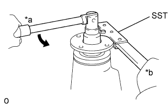
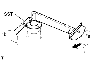
Text in Illustration *a Turn *b Hold Using SST and a socket wrench 30 mm, hold the rear drive pinion companion flange sub-assembly and remove the rear drive pinion nut.
- SST
- 09330-00021 ( 09330-00030 )
-
-
REMOVE REAR DRIVE PINION NUT (for 4 Pinion Gear Type)
-
Text in Illustration *a Turn *b Hold Using SST and a socket wrench 30 mm, hold the rear drive pinion companion flange sub-assembly and remove the rear drive pinion nut and the rear drive pinion plate washer.
- SST
- 09330-00021 ( 09330-00030 )
-
-
REMOVE REAR DRIVE PINION COMPANION FLANGE SUB-ASSEMBLY
Text in Illustration *a Turn *b Hold
-
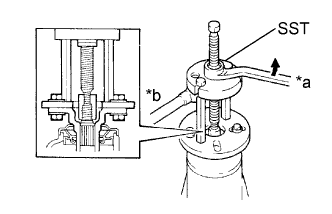
Using SST, remove the rear drive pinion companion flange sub-assembly.
- SST
- 09950-30012 ( 09951-03010, 09953-03010, 09954-03010, 09955-03030, 09956-03040 )
Note
Before using SST (center bolt), apply hypoid gear oil to its threads and tip.
-
-
INSTALL REAR DIFFERENTIAL CARRIER OIL SEAL
-
Using SST and a plastic-faced hammer, tap in a new oil seal until its surface is flush with the differential carrier end.
- SST
- 09223-78010
Standard oil seal depth -0.45 to 0.45 mm (-0.0177 to 0.0177 in.) -
Coat the lip of the oil seal with MP grease.
-
-
INSTALL REAR DRIVE PINION COMPANION FLANGE SUB-ASSEMBLY (for 2 Pinion Gear Type)
-
Text in Illustration *a Turn *b Hold Using SST, install the rear drive pinion companion flange sub-assembly.
- SST
- 09950-30012 ( 09951-03010, 09953-03010, 09954-03010, 09956-03030, 09955-03040 )
-
Coat the threads of the rear drive pinion nut with hypoid gear oil LSD.
-
Text in Illustration *a Turn *b Hold Using SST to hold the rear drive pinion companion flange sub-assembly, install the rear drive pinion nut.
- SST
- 09330-00021 ( 09330-00030 )
- Torque:
- 304 N*m { 3100 kgf*cm, 224 ft.*lbf }
-
-
INSTALL REAR DRIVE PINION COMPANION FLANGE SUB-ASSEMBLY (for 4 Pinion Gear Type)
-
Text in Illustration *a Turn *b Hold Using SST, install the rear drive pinion companion flange sub-assembly.
- SST
- 09950-30012 ( 09951-03010, 09953-03010, 09954-03010, 09955-03030, 09956-03040 )
-
Coat the threads of the rear drive pinion nut with hypoid gear oil LSD.
-
Text in Illustration *a Turn *b Hold Using SST to hold the rear drive pinion companion flange sub-assembly, install the rear drive pinion nut and the rear drive pinion plate washer.
- SST
- 09330-00021 ( 09330-00030 )
- Torque:
- 355 N*m { 3620 kgf*cm, 262 ft.*lbf }
-
-
INSPECT DIFFERENTIAL DRIVE PINION PRELOAD
-
Using a torque wrench, measure the preload of the backlash between the drive pinion and ring gear.
Standard Total Preload (at Starting) Type Bearing Specified Condition for 2 Pinion Gear New 1.80 to 3.17 N*m (19 to 32 kgf*cm, 16 to 28 in.*lbf) Reused 1.62 to 2.25 N*m (17 to 22 kgf*cm, 15 to 19 in.*lbf) for 4 Pinion Gear New 2.00 to 5.39 N*m (20 to 55 kgf*cm, 18 to 48 in.*lbf) Reused 1.00 to 2.76 N*m (10 to 28 kgf*cm, 8.9 to 24 in.*lbf) If the preload is not within the specification, refer to the tables in the "ADJUST DIFFERENTIAL DRIVE PINION PRELOAD" procedure to change the combination of the 2 shims.
-
-
INSPECT TOTAL PRELOAD
-
Using a torque wrench, measure the preload with the teeth of the drive pinion and ring gear in contact.
Standard Total Preload (at Starting) Type Bearing Specified Condition for 2 Pinion Gear New Standard drive pinion preload + 0.22 to 0.41 N*m (3 to 4 kgf*cm, 2 to 3 in.*lbf) Reused Standard drive pinion preload + 0.19 to 0.38 N*m (2.0 to 3.8 kgf*cm, 1.7 to 3.3 in.*lbf) for 4 Pinion Gear New or Reused Standard drive pinion preload + 0.20 to 0.39 N*m (2.1 to 3.9 kgf*cm, 1.8 to 3.4 in.*lbf)
-
-
INSPECT DIFFERENTIAL RING GEAR BACKLASH
-
Using a dial indicator, measure the backlash of the ring gear.
Standard backlash for 2 Pinion Gear Type 0.10 to 0.20 mm (0.00394 to 0.00787 in.) for 4 Pinion Gear Type 0.15 to 0.20 mm (0.00591 to 0.00787 in.) Tech Tips
Measure at 3 or more positions around the circumference of the ring gear.
-
If the backlash is not within the specification, adjust or repair the side bearing preload as necessary.
-
-
-
INSPECT RUNOUT OF REAR DRIVE PINION COMPANION FLANGE SUB-ASSEMBLY
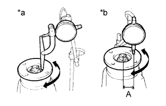
Text in Illustration *a Vertical Runout *b Horizontal Runout
-
Using a dial indicator, measure the vertical and horizontal runout of the rear drive pinion companion flange sub-assembly.
Distance from center to runout measurement point A for 2 Pinion Gear Type 30 mm (1.18 in.) for 4 Pinion Gear Type 35 mm (1.38 in.) Maximum Runout Type Runout Specified Condition for 2 Pinion Gear Vertical runout 0.10 mm (0.00394 in.) Lateral runout 0.10 mm (0.00394 in.) for 4 Pinion Gear Vertical runout 0.10 mm (0.00394 in.) Lateral runout 0.15 mm (0.00590 in.)
-
If the runout is greater than the maximum, replace the rear drive pinion companion flange sub-assembly.
-
-
-
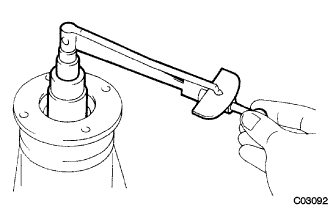
STAKE REAR DRIVE PINION NUT
-
Using a chisel and hammer, stake the rear drive pinion nut.
-
-
INSTALL REAR DIFFERENTIAL BEARING ADJUSTING NUT LOCK (for 4 Pinion Gear Type)
-
Install 2 new rear differential bearing adjust lock on the bearing caps.
- Torque:
- 13 N*m { 133 kgf*cm, 10 ft.*lbf }
-
After tightening bolts, bend the nut locks.
-