DIFFERENTIAL CARRIER ASSEMBLY (for Ring Gear Size 10.5 inch) DISASSEMBLY

-
FIX REAR DIFFERENTIAL CARRIER ASSEMBLY
-
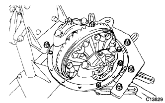
Fix the rear differential carrier assembly to the overhaul attachment.
-
-
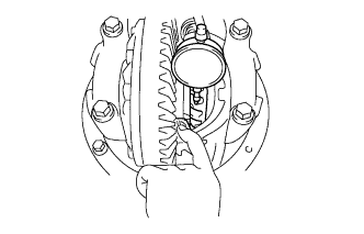
INSPECT RUNOUT OF REAR DRIVE PINION COMPANION FLANGE SUB-ASSEMBLY
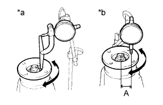
Text in Illustration *a Vertical Runout *b Horizontal Runout
-
Using a dial indicator, measure the vertical and horizontal runout of the rear drive pinion companion flange sub-assembly.
Distance from center to runout measurement point A for 2 Pinion Gear Type 30 mm (1.18 in.) for 4 Pinion Gear Type 35 mm (1.38 in.) Maximum Runout Type Runout Standard Condition for 2 Pinion Gear Vertical runout 0.10 mm (0.00394 in.) Horizontal runout 0.10 mm (0.00394 in.) for 4 Pinion Gear Vertical runout 0.10 mm (0.00394 in.) Horizontal runout 0.15 mm (0.00590 in.) If the runout is greater than the maximum, replace the rear drive pinion companion flange sub-assembly.
-
-
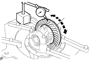
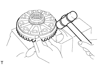
INSPECT RUNOUT OF DIFFERENTIAL RING GEAR
-
Using a dial indicator, measure the runout of the ring gear.
Maximum runout for 2 Pinion Gear Type 0.05 mm (0.00197 in.) for 4 Pinion Gear Type 0.01 mm (0.000393 in.) If the runout is greater than the maximum, replace the ring gear with a new one.
-
-
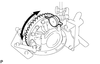
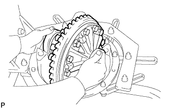
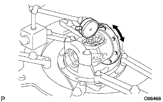
INSPECT DIFFERENTIAL RING GEAR BACKLASH
-
Using a dial indicator, measure the backlash of the ring gear.
Standard backlash for 2 Pinion Gear Type 0.10 to 0.20 mm (0.00394 to 0.00787 in.) for 4 Pinion Gear Type 0.15 to 0.20 mm (0.00591 to 0.00787 in.) Tech Tips
Measure at 3 or more positions around the circumference of the ring gear.
If the backlash is not within the specification, adjust or repair the side bearing preload as necessary.
-
-
INSPECT DIFFERENTIAL SIDE GEAR BACKLASH (for 2 Pinion Gear Type)
-
Using a dial indicator, measure the side gear backlash while holding one pinion gear toward the case.
Standard backlash 0.15 mm (0.00591 in.) or less If the backlash is not within the specification, replace the side gear thrust washer with one of a different thickness.
-
-
INSPECT DIFFERENTIAL DRIVE PINION PRELOAD
-
Using a torque wrench, measure the preload of the backlash between the drive pinion and ring gear.
Standard drive pinion preload (at starting) for 2 Pinion Gear Type 1.62 to 2.25 N*m (17 to 22 kgf*cm, 15 to 19 in.*lbf) for 4 Pinion Gear Type 1.00 to 2.76 N*m (10 to 28 kgf*cm, 8.9 to 24 in.*lbf) If necessary, disassemble and inspect the differential.
-
-
INSPECT TOTAL PRELOAD
-
Using a torque wrench, measure the total preload with the teeth of the drive pinion and ring gear in contact.
Standard total preload (at starting) for 2 Pinion Gear Type Standard drive pinion preload + 0.19 to 0.38 N*m (2.0 to 3.8 kgf*cm, 1.7 to 3.3 in.*lbf) for 4 Pinion Gear Type Standard drive pinion preload + 0.20 to 0.39 N*m (2.1 to 3.9 kgf*cm, 1.8 to 3.4 in.*lbf) If necessary, disassemble and inspect the differential.
-
-
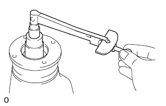
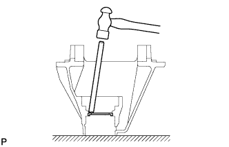
REMOVE REAR DRIVE PINION NUT (for 2 Pinion Gear Type)
-
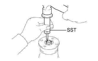
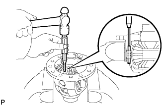
Using SST and a hammer, unstake the rear drive pinion nut.
- SST
- 09930-00010
Note
-
Be sure to use SST with the tapered end facing the shaft.
-
Do not grind SST tip with a grinder, etc.
-
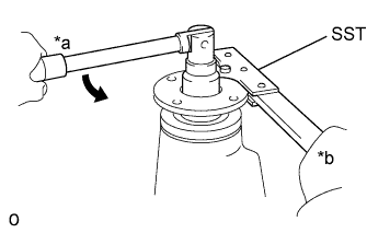
Text in Illustration *a Turn *b Hold Using SST and a socket wrench 30 mm, hold the rear drive pinion companion flange sub-assembly and remove the rear drive pinion nut.
- SST
- 09330-00021
-
-
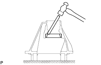
REMOVE REAR DRIVE PINION NUT (for 4 Pinion Gear Type)
-
Using SST and a hammer, unstake the rear drive pinion nut.
- SST
- 09930-00010
Note
-
Be sure to use SST with the tapered end facing the shaft.
-
Do not grind SST tip with a grinder, etc.
-
Text in Illustration *a Turn *b Hold Using SST and a socket wrench 30 mm, hold the rear drive pinion companion flange sub-assembly and remove the rear drive pinion nut and the rear drive pinion plate washer.
- SST
- 09330-00021
-
-
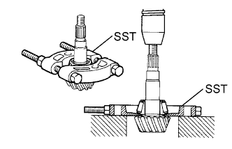
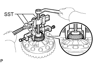
REMOVE REAR DRIVE PINION COMPANION FLANGE SUB-ASSEMBLY
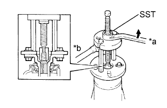
Text in Illustration *a Turn *b Hold
-
Using SST, remove the rear drive pinion companion flange sub-assembly.
- SST
- 09950-30012 ( 09951-03010, 09953-03010, 09954-03010, 09955-03030, 09956-03040 )
Note
Before using SST (center bolt), apply hypoid gear oil to its threads and tip.
-
-
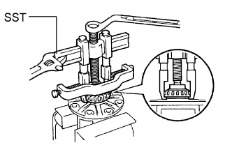
REMOVE REAR DIFFERENTIAL CARRIER OIL SEAL
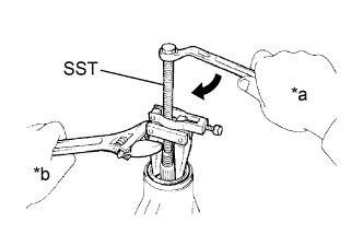
Text in Illustration *a Turn *b Hold
-
Using SST, remove the rear differential carrier oil seal from the differential carrier.
- SST
- 09308-10010
Note
Before using SST (center bolt), apply hypoid gear oil to its threads and tip.
-
-
REMOVE REAR DIFFERENTIAL DRIVE PINION OIL SLINGER
-
Remove the rear differential drive pinion oil slinger.
-
-
REMOVE REAR DRIVE PINION FRONT TAPERED ROLLER BEARING (for 2 Pinion Gear Type)
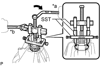
Text in Illustration *a Turn *b Hold
-
Using SST, remove the rear drive pinion front tapered roller bearing (inner race) from the drive pinion.
- SST
- 09950-40011 ( 09951-04010, 09953-04020, 09952-04010 )
- 09955-04130
- 09958-04020
Note
Before using SST (center bolt), apply hypoid gear oil to its threads and tip.
-
Remove the 2 preload adjusting shims.
-
-
REMOVE REAR DRIVE PINION FRONT TAPERED ROLLER BEARING (for 4 Pinion Gear Type)
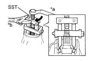
Text in Illustration *a Turn *b Hold
-
Using SST, remove the rear drive pinion front tapered roller bearing (inner race) from the drive pinion.
- SST
- 09556-22010
Note
Before using SST (center bolt), apply hypoid gear oil to its threads and tip.
-
Remove the 2 rear differential drive pinion spacer adjust shims.
-
-
REMOVE REAR DIFFERENTIAL CASE ASSEMBLY (for 2 Pinion Gear Type)
-
Text in Illustration *a Matchmark Place matchmarks on the bearing cap and the differential carrier.
-
Remove the 4 bolts and the 2 bearing caps.
-
Using SST and a plastic hammer, remove the 2 side bearing plate washers.
- SST
- 09504-22011
Tech Tips
Measure the plate washer thickness and note it down.
-
Remove the differential case with the 2 case bearing outer races from the differential carrier.
Tech Tips
Tag the case bearing outer races to show the location for reassembling.
-
-
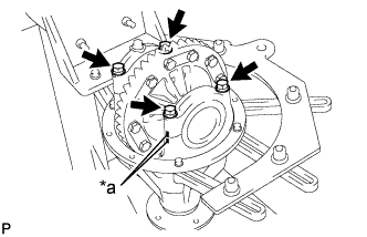
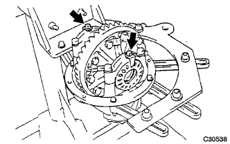
REMOVE REAR DIFFERENTIAL BEARING ADJUSTING NUT LOCK (for 4 Pinion Gear Type)
-
Remove the 2 bolts and the 2 rear differential bearing adjusting nut locks.
-
-
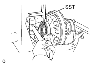
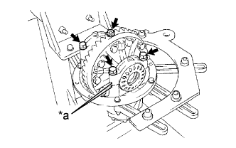
REMOVE REAR DIFFERENTIAL CASE ASSEMBLY (for 4 Pinion Gear Type)
-
Place matchmarks on the bearing cap and the differential carrier.
Text in Illustration *a Matchmark -
Remove the 4 bolts and the 2 bearing caps.
-
Remove the 2 rear differential bearing adjusting nuts.
-
Remove the rear differential case assembly and the 2 case bearing outer races from the differential carrier.
Tech Tips
Tag the 2 case bearing outer races to show the location for reassembling.
-
-
REMOVE REAR DIFFERENTIAL DRIVE PINION
-
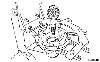
Remove the differential drive pinion and the spacer from the differential carrier.
-
-
REMOVE REAR DRIVE PINION REAR TAPERED ROLLER BEARING
-
Using SST and a press, remove the rear drive pinion rear tapered roller bearing (inner race) from the drive pinion.
- SST
- 09950-00020
Tech Tips
If the drive pinion or ring gear are damaged, replace them as a set.
-
-
REMOVE REAR DIFFERENTIAL DRIVE PINION PLATE WASHER
-
Remove the plate washer from the drive pinion.
-
-
REMOVE REAR DRIVE PINION FRONT TAPERED ROLLER BEARING
-
Using SST, remove the rear drive pinion front tapered roller bearing outer race.
- SST
- 09308-00010
Tech Tips
If the bearing is damaged during removal, replace it.
-
-
REMOVE DIFFERENTIAL OIL STORAGE RING
-
Using a brass bar and a hammer, tap out the storage ring.
-
-
REMOVE REAR DRIVE PINION REAR TAPERED ROLLER BEARING
-
Using a brass bar and a hammer, tap out the rear drive pinion rear tapered roller bearing outer race.
Tech Tips
If the bearing is damaged during removal, replace it.
-
-
REMOVE DIFFERENTIAL RING GEAR (for 2 Pinion Gear Type)
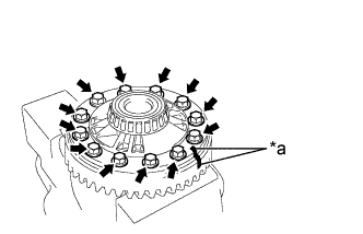
Text in Illustration *a Matchmark
-
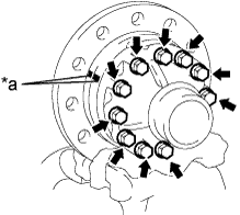
Place matchmarks on the ring gear and the differential case.
-
Remove the 12 ring gear set bolts.
-
Using a plastic-faced hammer, tap on the ring gear to separate it from the differential case.
-
-
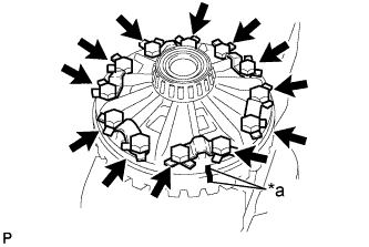
REMOVE DIFFERENTIAL RING GEAR (for 4 Pinion Gear Type)
-
Place matchmarks on the ring gear and the differential case.
Text in Illustration *a Matchmark -
Using a screwdriver and a hammer, pry out the lock plates.
-
Remove the 12 ring gear set bolts and the 6 lock plates.
-
Using a plastic hammer, tap on the ring gear to separate it from the differential case.
-
-
INSPECT REAR DIFFERENTIAL CASE ASSEMBLY RUNOUT
-
Install the differential case to the differential carrier.
-
Inspect the differential case runout.
Maximum runout for 2 Pinion Gear Type 0.04 mm (0.00158 in.) for 4 Pinion Gear Type 0.05 mm (0.00197 in.) -
Remove the differential case from the differential carrier.
-
-
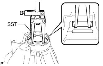
REMOVE REAR DIFFERENTIAL CASE BEARING (for 2 Pinion Gear Type)
-
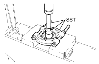
Using SST, remove the 2 rear differential case bearings from the differential case.
- SST
- 09950-40011 ( 09951-04010, 09952-04010, 09953-04020, 09954-04010, 09957-04010, 09958-04011 )
- 09950-60010 ( 09951-00500 )
- 09955-04120
Note
Before using SST (center bolt), apply hypoid gear oil to its threads and tip.
Tech Tips
Fix the claws of SST to the notches in the differential case.
-
-
REMOVE REAR DIFFERENTIAL CASE BEARING (for 4 Pinion Gear Type)
-
Using SST, remove the 2 rear differential case bearings from the differential case.
- SST
- 09950-40011 ( 09951-04020, 09952-04010, 09953-04030, 09954-04010, 09955-04061, 09957-04010, 09958-04011 )
- 09950-60010 ( 09951-00480 )
Note
Before using SST (center bolt), apply hypoid gear oil to its threads and tip.
-
-
REMOVE DIFFERENTIAL CASE (for 2 Pinion Gear Type)
-
Using a pin punch 5 mm and hammer, tap out the straight pin.
-
Remove the pinion shaft, 2 pinion gears, 2 pinion gear thrust washers, 2 side gears and the 2 side gear thrust washers.
-
-
REMOVE DIFFERENTIAL CASE (for 4 Pinion Gear Type)
Text in Illustration *a Matchmark
-
Place matchmarks on the LH and RH cases.
-
Remove the 12 bolts.
-
Using a plastic hammer, separate the LH and RH cases.
-
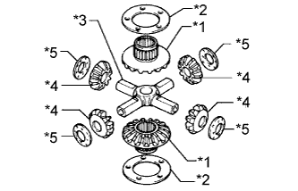
*1 Rear Differential Side Gear *2 Rear Differential Side Gear Thrust Washer *3 Rear Differential Spider *4 Rear Differential Pinion *5 Rear Differential Pinion Thrust Washer Remove these parts from the differential case.
-
-
REMOVE REAR DIFFERENTIAL DUST DEFLECTOR
-
Using SST and a press, press out the dust deflector.
- SST
- 09950-00020
- 09950-60010 ( 09951-00480 )
- 09950-70010 ( 09951-07150 )
Note
Do not drop the rear drive pinion companion flange sub-assembly.
-
-
INSPECT DIFFERENTIAL PINION AND SIDE GEAR
-
Check that no damage is identified on the differential pinion and the differential side gear.
If the differential pinion and/or differential side gear is damaged, replace the differential.
-
-
INSPECT DIFFERENTIAL CASE
-
Check that no damaged is differential case.
If the differential case is damaged, replace the differential case.
-