PROPELLER SHAFT ASSEMBLY (for 3 Joint Type) INSTALLATION

-
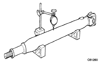
INSPECT PROPELLER SHAFT ASSEMBLY REAR
-
Using a dial indicator, check the shaft runout.
Maximum runout Length of propeller shaft tube 800 mm more than 0.4 mm (0.016 in.) 800 mm less than 0.3 mm (0.012 in.) If the shaft runout is greater than maximum, replace the shaft.
-
-
INSPECT INTERMEDIATE SHAFT
-
When replacing the spider bearing, be sure that the grease fitting assembly hole is facing to the direction shown in the illustration.
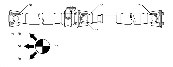
Text in Illustration *a No. 1 *b No. 2 *c No. 3 *d Sleeve yoke *e The figure on the left shows the locations of the grease fittings as seen from the rear * - Tech Tips
Fill up the grease fitting with MP grease.
-
-
INSTALL INTERMEDIATE SHAFT
-
After align the matchmarks of the brake drum and propeller intermediate shaft, install the 4 nuts and washers.
Text in Illustration *a Matchmark - Torque:
- 88 N*m { 897 kgf*cm, 65 ft.*lbf }
-
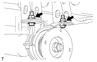
Fully tighten the 2 nuts.
- Torque:
- 37 N*m { 370 kgf*cm, 27 ft.*lbf }
-
Text in Illustration *a Matchmark Align the matchmarks on the propeller intermediate shaft and propeller shaft assembly.
-
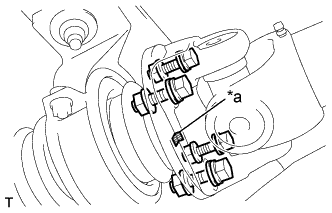
Install the 4 bolts, washers and nuts.
- Torque:
- 88 N*m { 897 kgf*cm, 65 ft.*lbf }
-
-
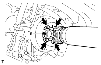
INSTALL PROPELLER SHAFT ASSEMBLY REAR
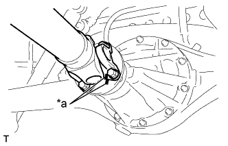
Text in Illustration *a Matchmark
-
Align the matchmarks on the propeller shaft flange and differential.
-
Install the 4 bolts, washers and nuts.
- Torque:
- 88 N*m { 897 kgf*cm, 65 ft.*lbf }
-