PROPELLER SHAFT ASSEMBLY (for 3 Joint Type) REASSEMBLY

-
INSTALL UNIVERSAL JOINT SPIDER ASSEMBLY
-
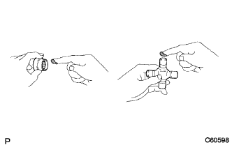
Apply MP grease to a new spider and bearings.
-
Install the bearing case with needle roller bearing to the spider.
-
Align the matchmarks on the yoke with the one the sleeve.
-
Fit the spider into the yoke.
-
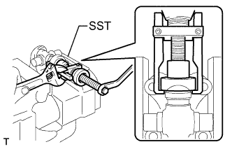
Using SST, install the bearings on the spider.
- SST
- 09332-25010
-
Using SST, adjust both bearings so that the snap ring grooves are at maximum and equal in width.
- SST
- 09332-25010
-
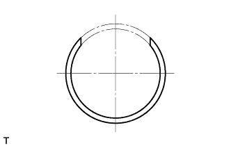
Install the 4 new snap rings of equal thickness which will allow no axial play.
Tech Tips
Do not reuse the snap rings.
Thickness of snap ring (Both ends thin type) Mark Thickness mm (in.) - 1.985 - 2.015 (0.781 - 0.793) Light Brown 2.015 - 2.045 (0.793 - 0.805) Blue 2.045 - 2.075 (0.805 - 0.817) - 2.075 - 2.105 (0.817 - 0.829) Note
-
Must use a new retainer ring.
-
Must use retainer rings of the same thickness as possible on both ends.
-
-
Using a hammer, tap the yoke until there is no clearance between the bearing outer race and snap ring.
Tech Tips
Install a new spider bearing on the sleeve side in the procedure described above.
-
-
INSPECT UNIVERSAL JOINT SPIDER ASSEMBLY
-
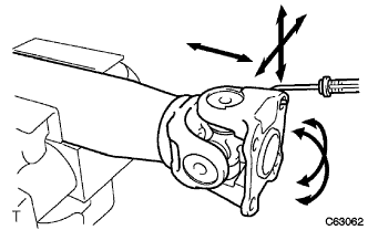
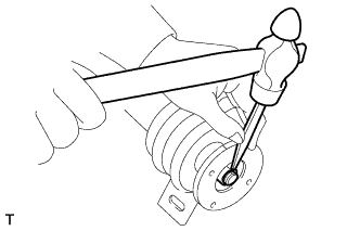
Using a spring tension gauge, hang the hook of the spring tension gauge on the bolt hole of the flange yoke and measure the rotating force.
Standard rotating torque (at starting) 2KD-FTV 0.5 - 2.8 N*m (5.1 - 28.5 kgf*cm, 4.4 - 24.7 in.*lbf) Except 2KD-FTV Maximum 1.1 N*m (11.2 kgf*cm, 9.68 in.*lbf) Note
Measurement of rotating force should be done at 2 positions for each universal joint by 90° on the opposite directions (flange yoke side and end yoke side). When the rotating force is lighter than the standard, use one lank thicker retainer ring and one lank thinner retainer ring when it is heavier.
-
-
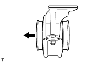
INSTALL CENTER SUPPORT BEARING ASSEMBLY NO.1
-
Install the center support bearing assembly to the intermediate shaft.
Text in Illustration 
Front -
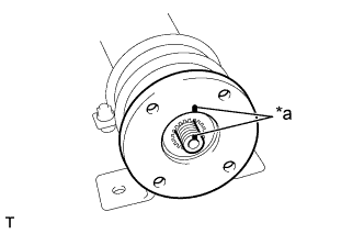
Text in Illustration *a Matchmark Align the matchmarks on the flange coupling and intermediate shaft.
-
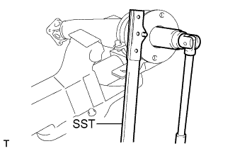
Using SST and a socket wrench, tighten a new lock nut.
- SST
- 09330-00021
-
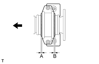
In off-vehicle condition, adjust the position of cushion rubber so that the position will come to the center of the housing (A = B), then tighten the support bearing bracket installation nut.
Text in Illustration Front - Torque:
- 167 N*m { 1703 kgf*cm, 123 ft.*lbf }
-
After installation, check that the center line of the bracket is vertical to the intermediate axis.
-
Using a chisel and a hammer, stake the lock nut.
-
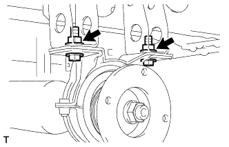
Install the center support bearing bracket with the 2 bolts and temporally tighten the 2 nuts.
-