PROPELLER SHAFT ASSEMBLY (for 3 Joint Type) DISASSEMBLY

-
REMOVE CENTER SUPPORT BEARING ASSEMBLY NO.1
-
Fix the flange coupling at the center bearing section with a vice.
-
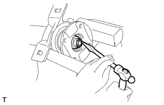
Using chisel and hammer, loosen the staked part of the lock nut.
Note
Loosen the staked part of the lock nut completely, otherwise the screw of the propeller shaft may be damaged.
-
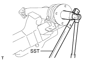
Using SST and a socket wrench, remove the nut and spring washer.
- SST
- 09330-00021
-
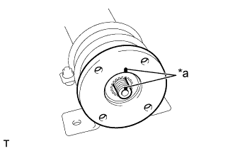
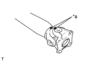
Text in Illustration *a Matchmark Place matchmarks on the intermediate shaft and flange coupling.
-
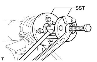
Using SST, separate the flange coupling from the intermediate shaft.
- SST
- 09950-30012 ( 09951-03010, 09953-03010, 09954-03010, 09955-03030, 09956-03030 )
-
Remove the center support bearing assembly.
-
-
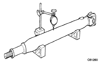
INSPECT PROPELLER SHAFT ASSEMBLY REAR
-
Using a dial indicator, check the shaft runout.
Maximum runout Length of propeller shaft tube 800 mm more than 0.4 mm (0.016 in.) 800 mm less than 0.3 mm (0.012 in.) If the shaft runout is greater than maximum, replace the shaft.
-
-
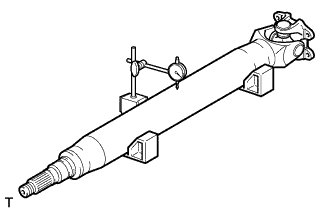
INSPECT INTERMEDIATE SHAFT
-
Using a dial indicator, check the shaft runout.
Maximum runout 0.8 mm (0.031 in.) If the shaft runout is greater than maximum, replace the shaft.
-
-
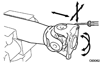
INSPECT UNIVERSAL JOINT SPIDER ASSEMBLY
-
Using a spring tension gauge, hang the hook of the spring tension gauge on the bolt hole of the flange yoke and measure the rotating force.
Standard rotating torque (at starting) 2KD-FTV 0.5 - 2.8 N*m (5.1 - 28.5 kgf*cm, 4.4 - 24.7 in.*lbf) Except 2KD-FTV Maximum 1.1 N*m (11.2 kgf*cm, 9.68 in.*lbf) Note
Measurement of rotating force should be done at 2 positions for each universal joint by 90° on the opposite directions (flange yoke side and end yoke side). When the rotating force is lighter than the standard, use one lank thicker retainer ring and one lank thinner retainer ring when it is heavier.
-
-
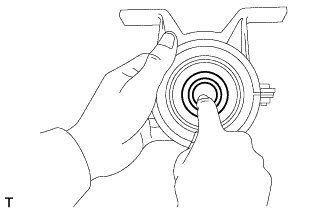
INSPECT CENTER SUPPORT BEARING ASSEMBLY NO.1
-
When turning the center bearing with hand, check that it turns smoothly without catching and there is no crack or damage.
If there is any defect, change it.
-
In case that there is any damage in the lip of the center bearing case, change it.
Note
Do not soak the center bearing in the cleaner.
-
-
REMOVE UNIVERSAL JOINT SPIDER ASSEMBLY
-
Place matchmarks on the flange yoke and sleeve yoke.
Text in Illustration *a Matchmark -
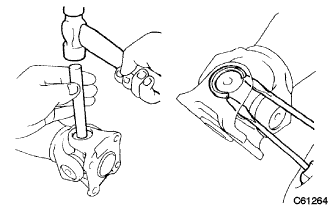
Using a brass bar and a hammer, slightly tap in the bearing outer races.
-
Using 2 screwdrivers, remove the 4 snap rings from the grooves.
-
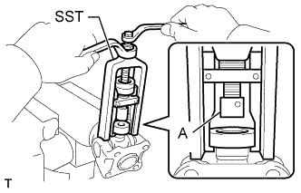
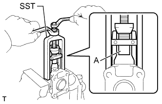
Using SST, push out the bearing from the propeller shaft.
- SST
- 09332-25010
Tech Tips
Sufficiently raise the part indicated by (A) so that it does not come into contact with the bearing.
-
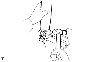
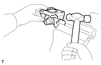
Clamp the bearing outer race in a vise and tap off the propeller shaft with a hammer.
Note
Do not tap the shaft.
Tech Tips
Remove the bearing on opposite side in the same procedure.
-
Install the 2 removed bearing outer race to the spider.
-
Using SST, push out the bearing from the yoke.
- SST
- 09332-25010
Tech Tips
Sufficiently raise the part indicated by (A) so that it does not come into contact with the bearing.
-
Clamp the outer bearing race in a vise and tap off the yoke with a hammer.
-